SOUVIK RAY BARUAH

Architect · Master of Advanced Architecture, IAAC Barcelona

Souvik Ray Baruah

Architect working between the construction site, computational design and robotic fabrication: from a 50,000-seat stadium and a year on an L&T building site to modular housing and binder-free straw walls in Barcelona.

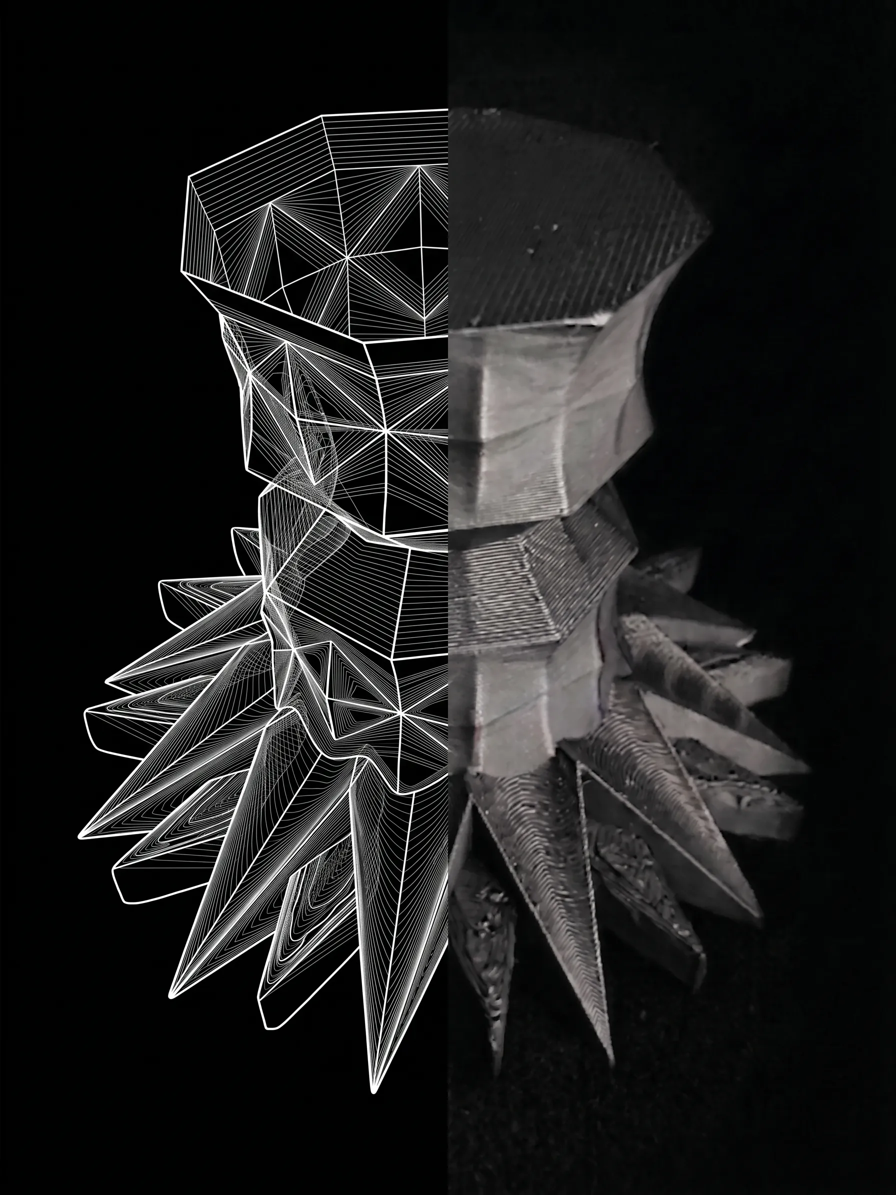
Faceted parametric sculpture shown half as wireframe, half as rendered model
5projects in this portfolio
IAACMAA02, 2025 – 2027
NIT TrichyB.Arch, CGPA 8.04
L&T1 year on site, 2024 – 2025

About me

Master of Advanced Architecture student, Barcelona, Spain

My journey as a professional architect began on site, where I was exposed to construction and execution of proposed design on paper. My experience on site led me to understand the importance of developing systems rather than just design and advancing towards an era of AI integrated workflows.

Education

Institute for Advanced Architecture of CataloniaBarcelona, Spain
  • Master of Advanced Architecture (MAA02)
  • September 2025 – expected July 2027
  • Design research studio: Robotics for Ecological Buildings
National Institute of TechnologyTiruchirappalli, India
  • Bachelor of Architecture
  • July 2019 – July 2024
  • First-class degree, CGPA 8.04

Professional experience

Larsen & Toubro ConstructionVadodara, India
  • Graduate architect trainee
  • August 2024 – June 2025
  • Site-based design coordinator
2+ Design CollaborativeMysuru, India
  • Architectural intern
  • January 2023 – June 2023
  • Residential, commercial and masterplan projects

Skills

RhinocerosProficient
GrasshopperProficient
AutoCADProficient
RevitIntermediate
LumionProficient
FigmaProficient
Adobe SuiteProficient

Fabrication

3D printingCNCLaser cuttingRobotics

Competitions

GSen Trophy, NASA 2022Team head · National Association of Students of Architecture
ANDC Trophy, NASA 2021Co-head · National Association of Students of Architecture
BRICK Awards 24Illustrator, as a member of 2+ Design Collaborative, 2023
1

InBetween: Housing for 2050
Term 1 design project, IAAC (group)Barcelona, SpainRoles: computational logic building, Ladybug analysis, Rhino 3D modelling, physical prototyping
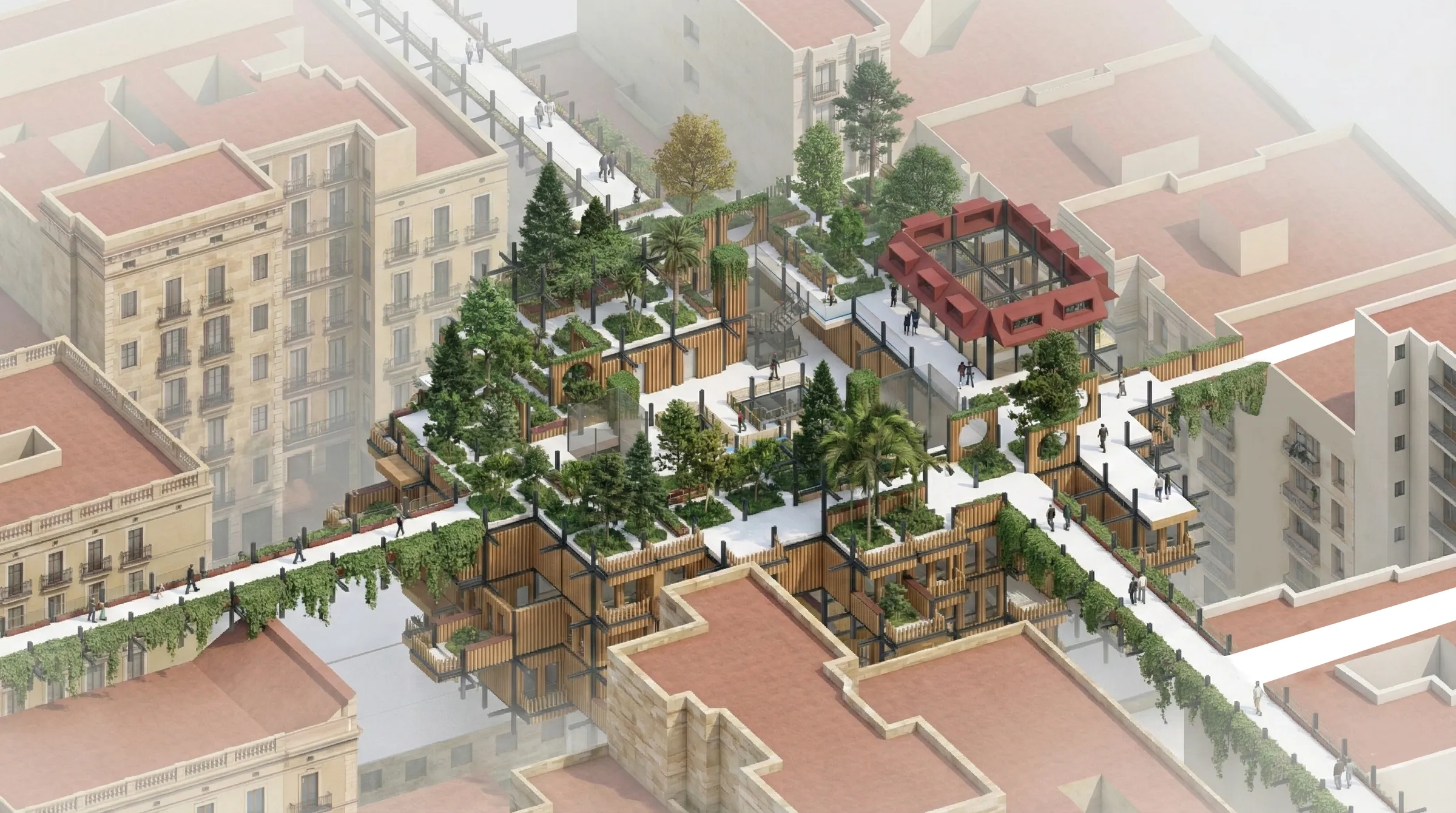
Aerial render of timber housing modules and green rooftops inserted between Cerdà blocks

Project description

A temporary layer between the blocks

The project proposes a transitional housing system for people arriving in Barcelona for work or study, including students, young professionals and temporary workers. It responds to the growing demand for short-term and interim living in a city under increasing demographic and housing pressure.

The system introduces a modular, temporary living layer inserted in between existing urban blocks, activating underused spaces without permanent construction.
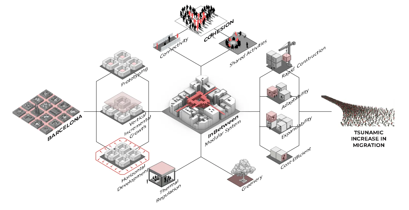
Concept diagram of the InBetween system

Growth logic

Pseudo code to growth pattern

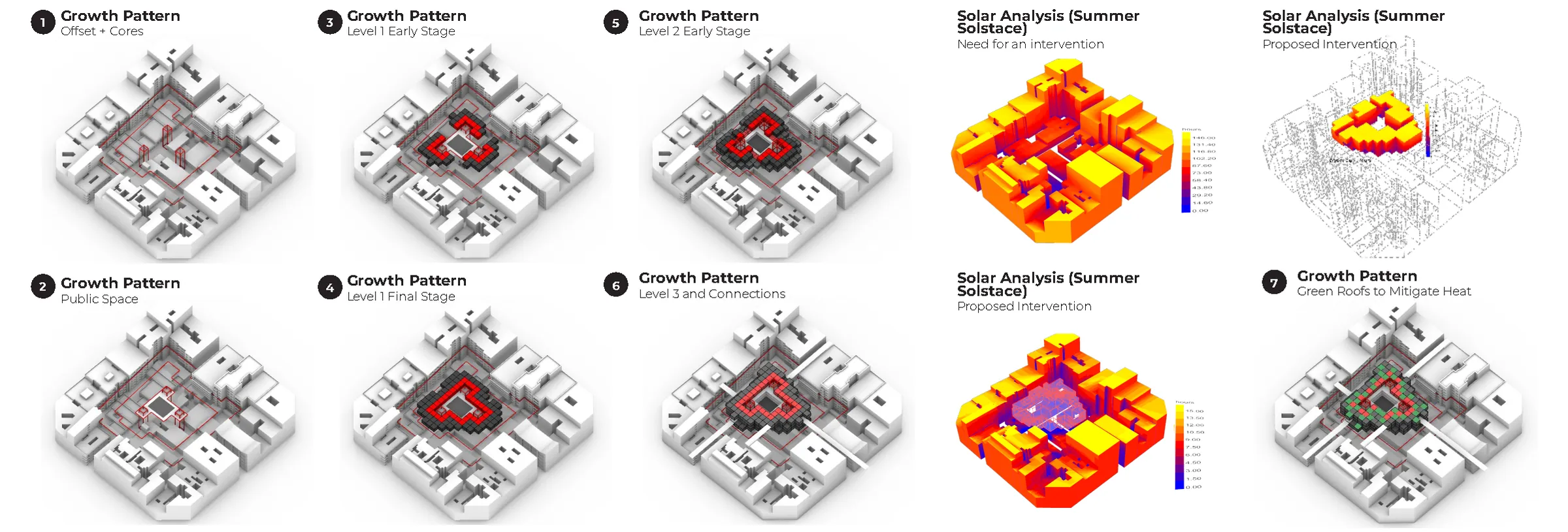
A rule-based script grows the housing from the shafts outward, culling points and stacking voxels floor by floor, then tests each option for courtyard sunlight, incident radiation and outward views with Ladybug.
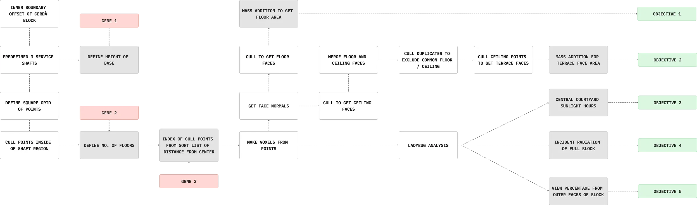
Flowchart of the growth logic
Growth pattern stages and solar analysis

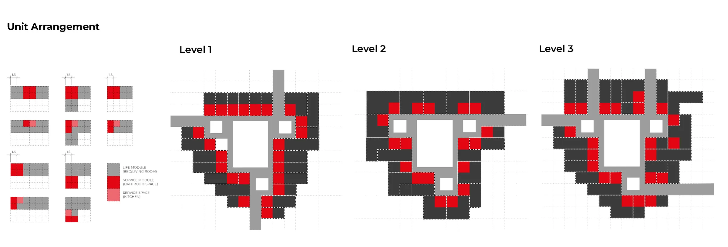
Layout and increment logic

Rules that keep it liveable

Access and placement
  • Main access fixed from the shafts leading to the alleyways on ground level.
  • Offset from existing buildings set at 9 m.
  • Minimum height from the ground is 13 m.
  • Shafts connect together to form the access.
  • Communal space at the centre.
  • All services and access around the shafts.
Parameters of increment
  • A housing unit has at least 1 living unit and 1 service unit.
  • All living units are accessed through a service unit.
  • All windows face outwards.
  • When a floor reaches its maximum boundary, the next floor grows along the shaft.
  • The intervention connects to the surrounding buildings and city.
  • Rooftops are always green and public.
Housing unit division and layout plans

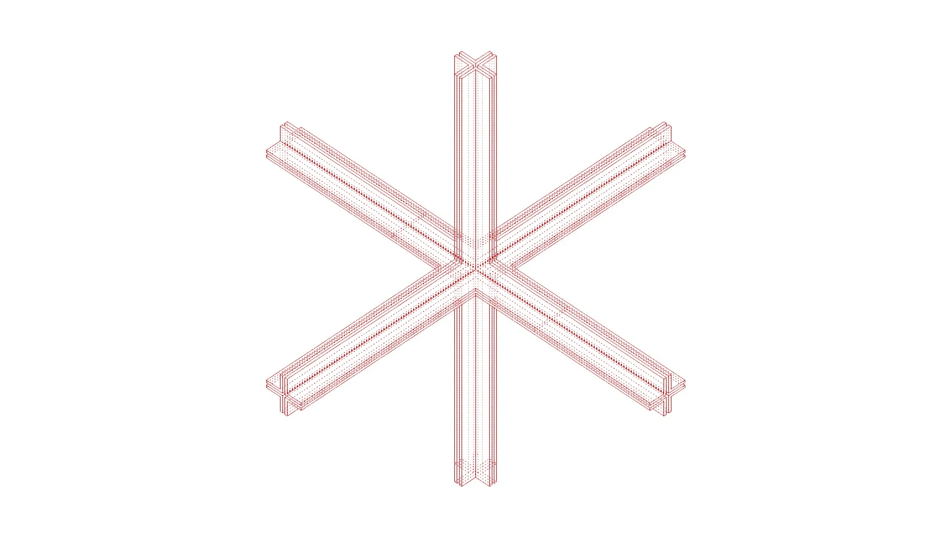
Technical joinery details

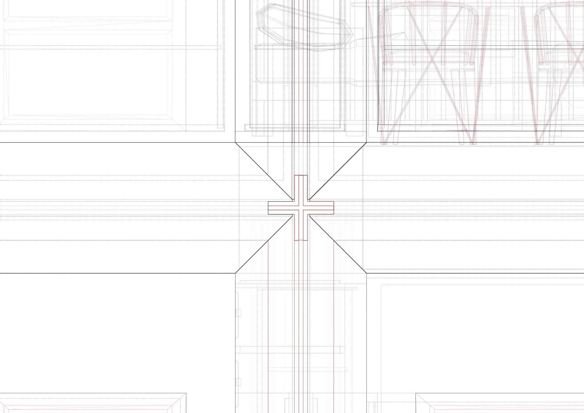
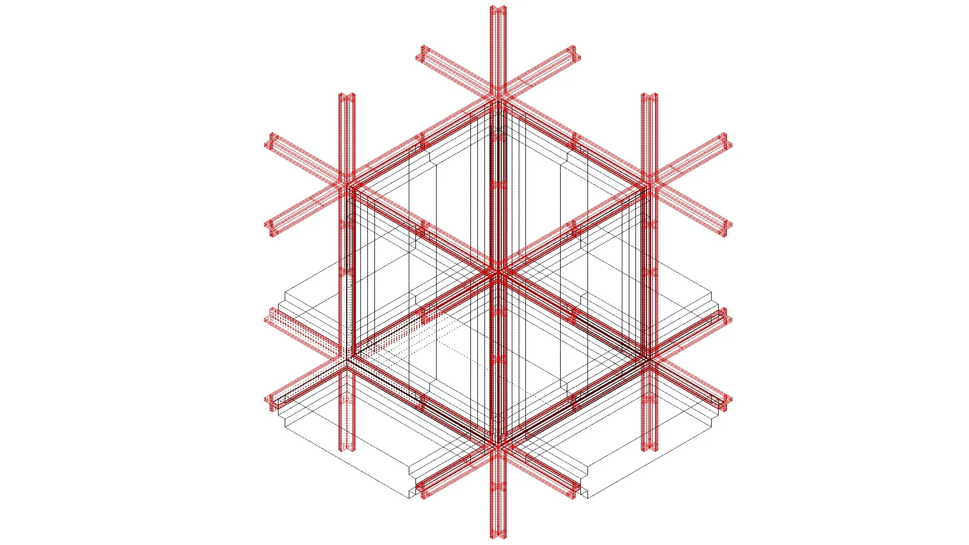
One cruciform node

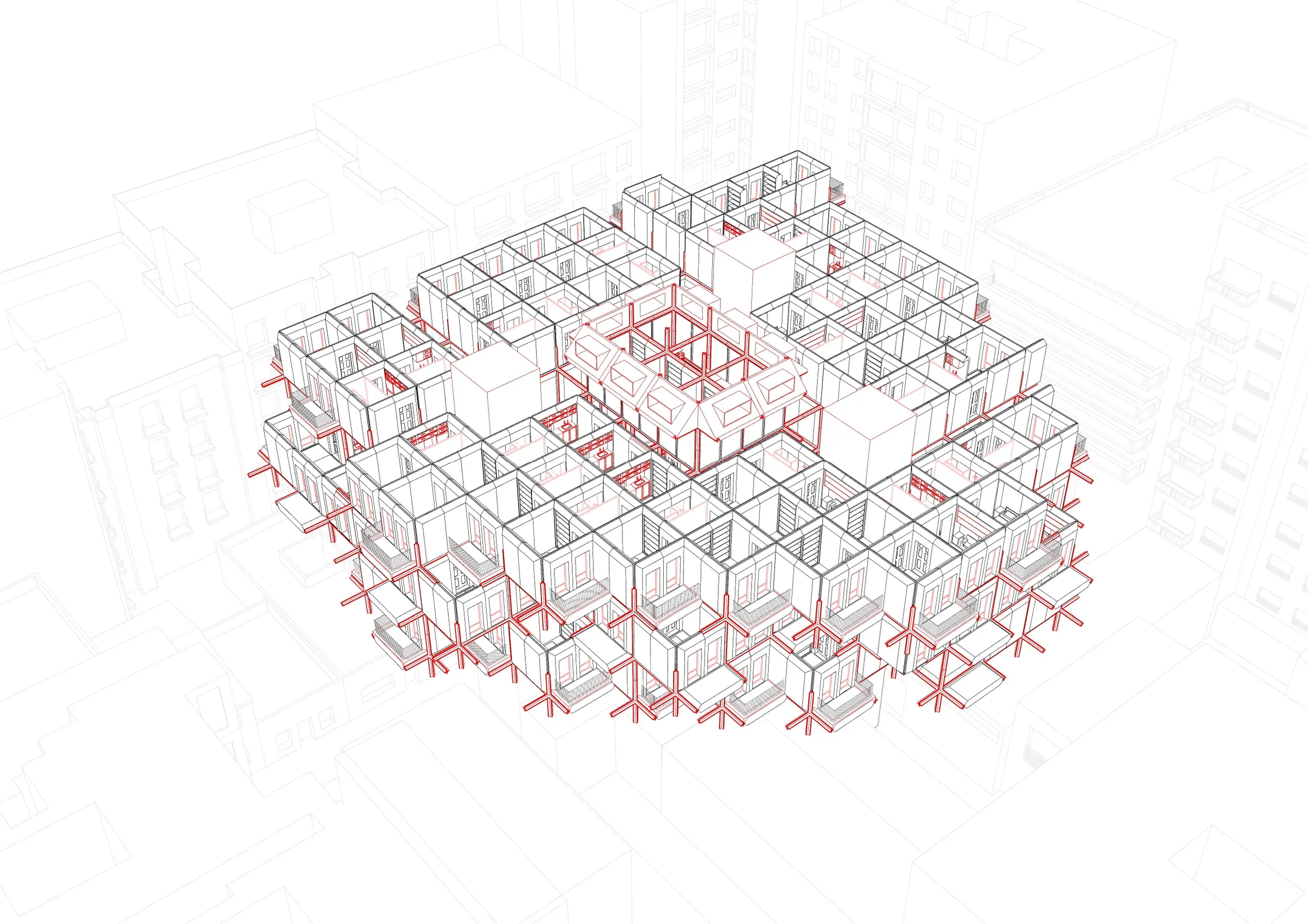
At every intersection, a cruciform connector joins the corners of four adjacent modules into one node. The module corners are chamfered to leave room for the connector and keep the junction compact. A vertical member runs through the node and carries load down the stack.
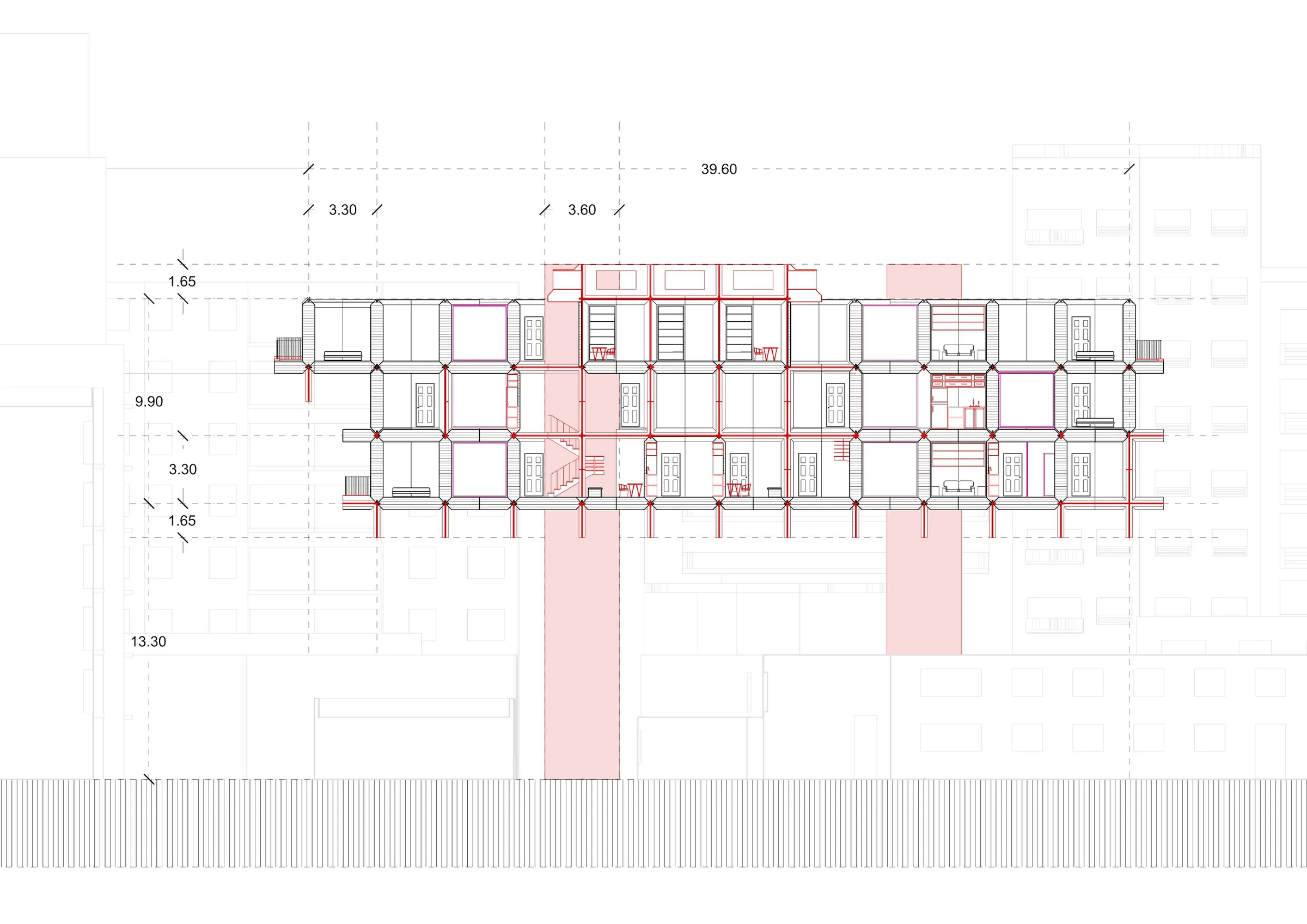
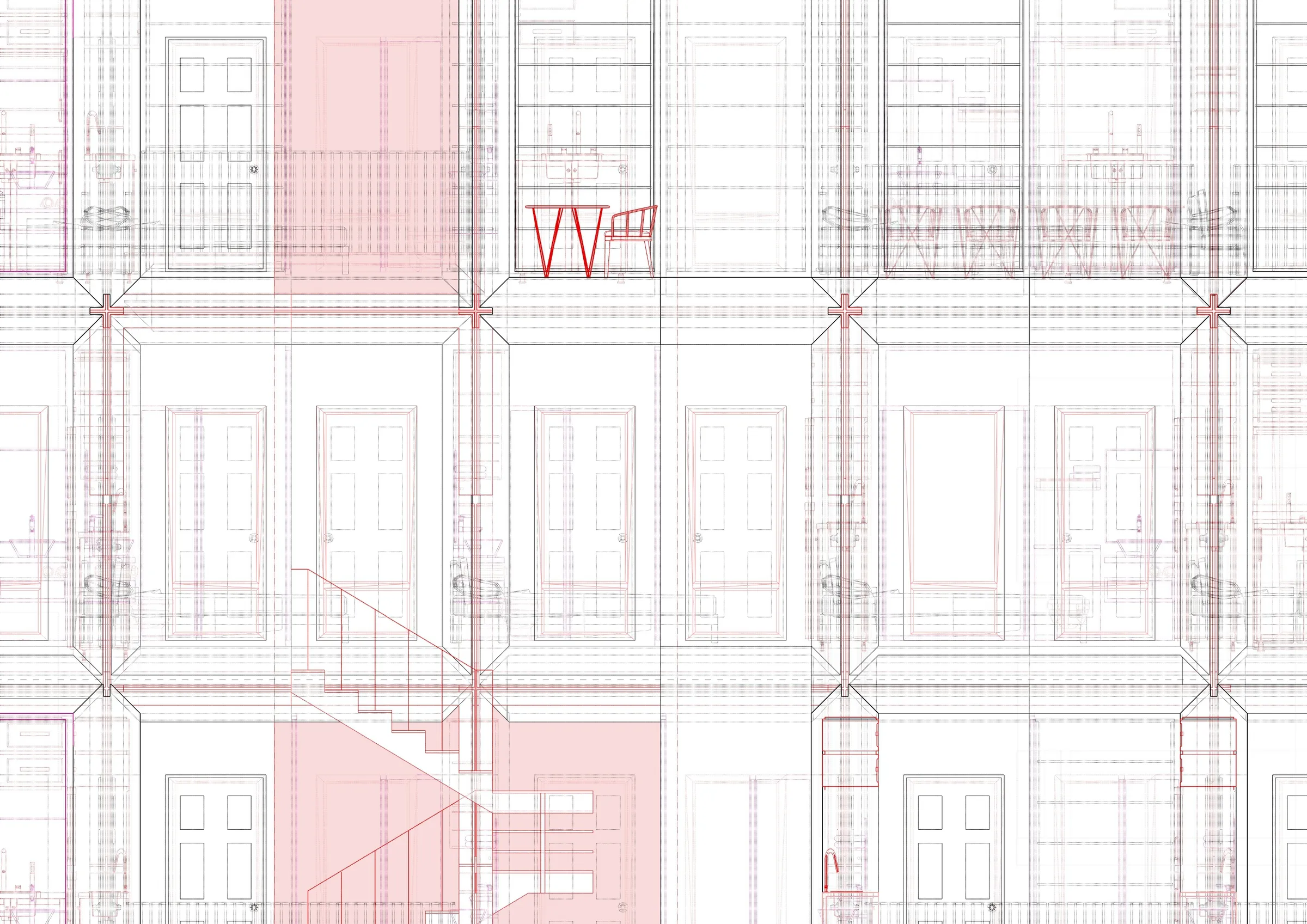
Section drawing
Section through stacked living and service units
Isometric of one block unit
Isometric: 1 block unit
Isometric of the cruciform joint
Isometric: cruciform joint
Living system connection drawing
Living system: how each block is connected
Cruciform joint detail
Joint detail: the cruciform joint

Kit of parts

Demountable walls

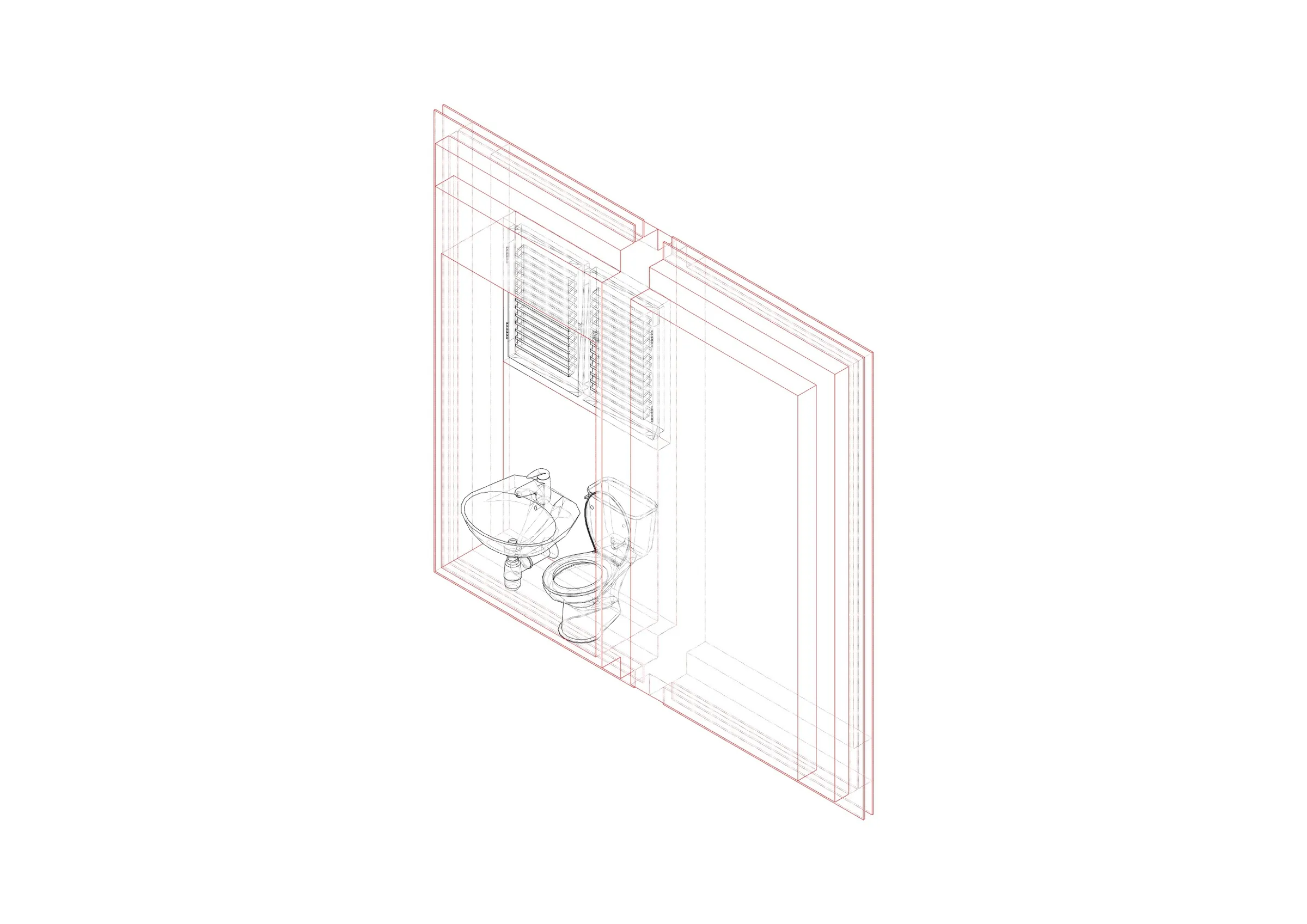
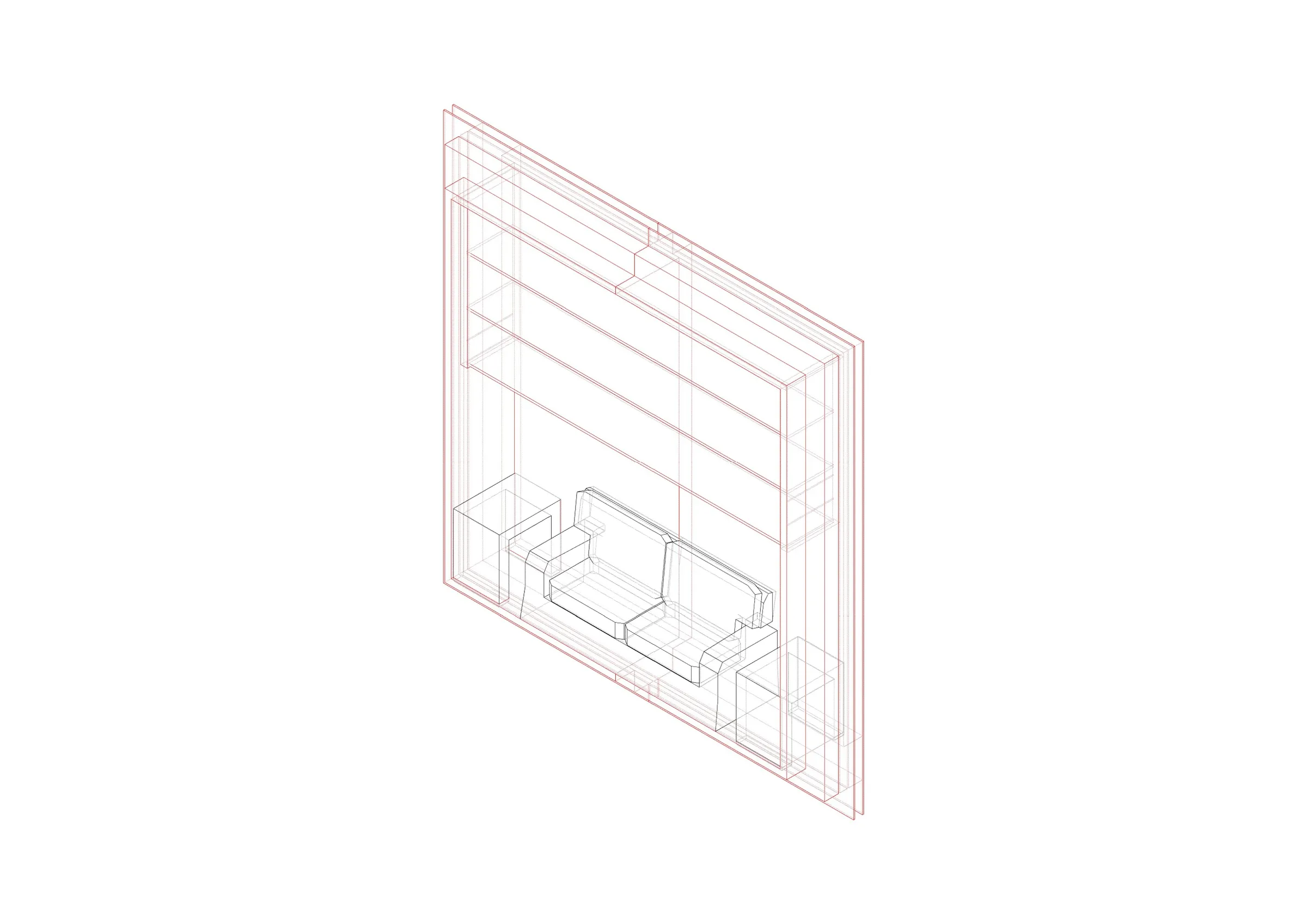
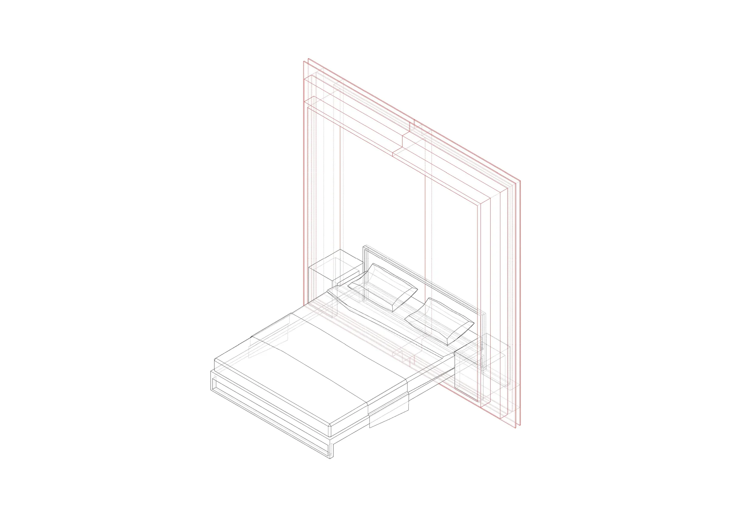
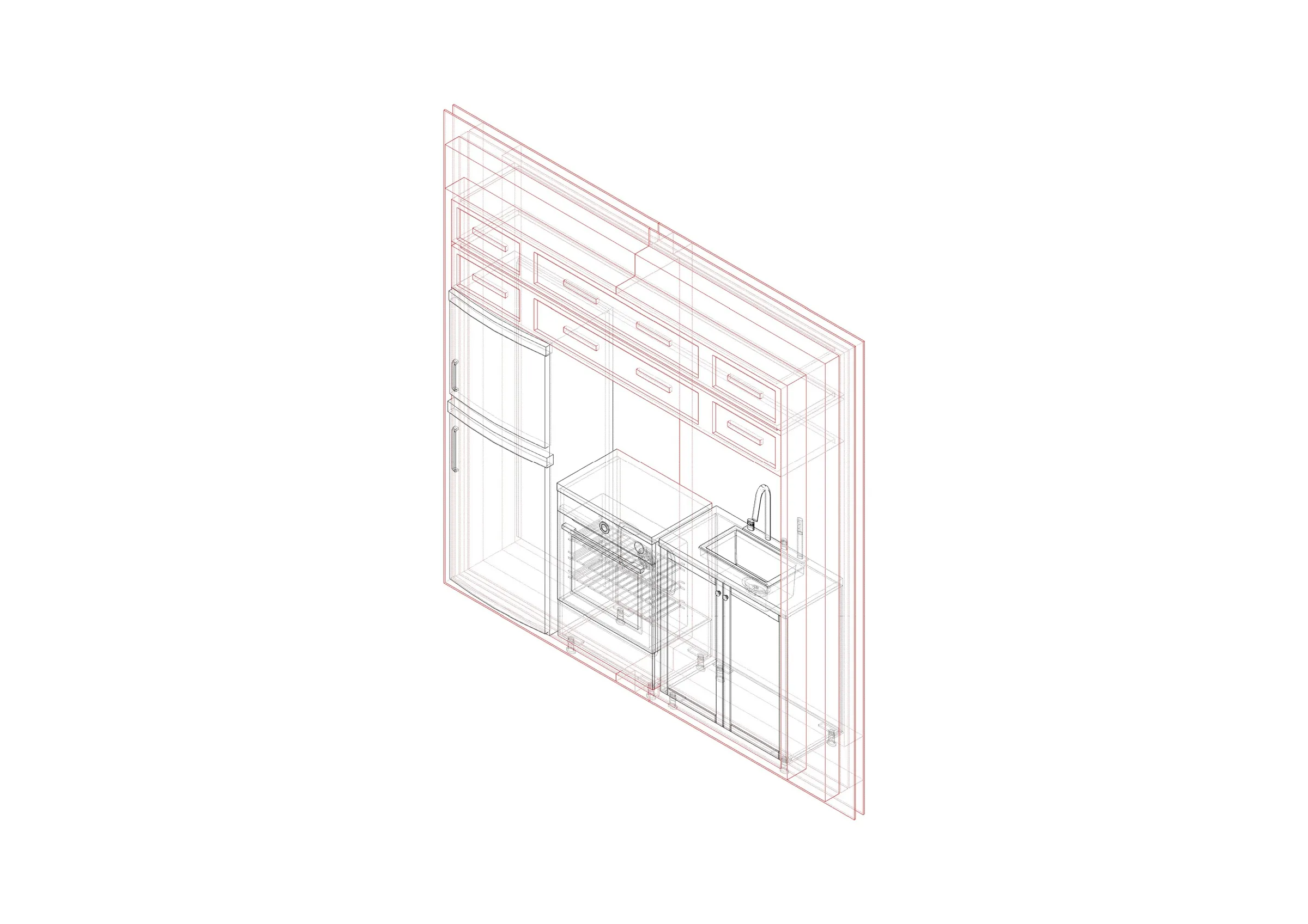
The kit of parts splits each home into distinct wall types: service, living and bed walls. Service units hold the wet core of WC, basin and kitchenette, and also act as each home's entrance. Living units carry built-in storage and shelving, keeping the floor area free. A communal dining space at the centre of each cluster brings residents together.
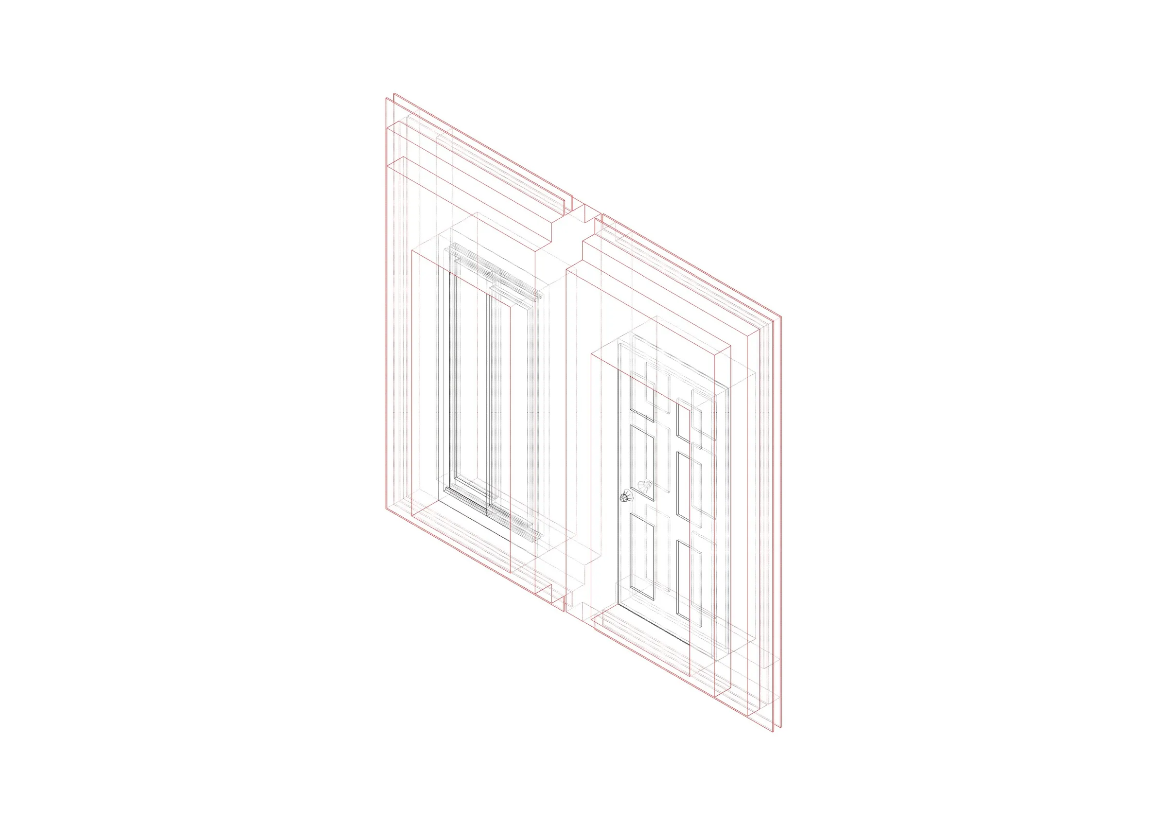
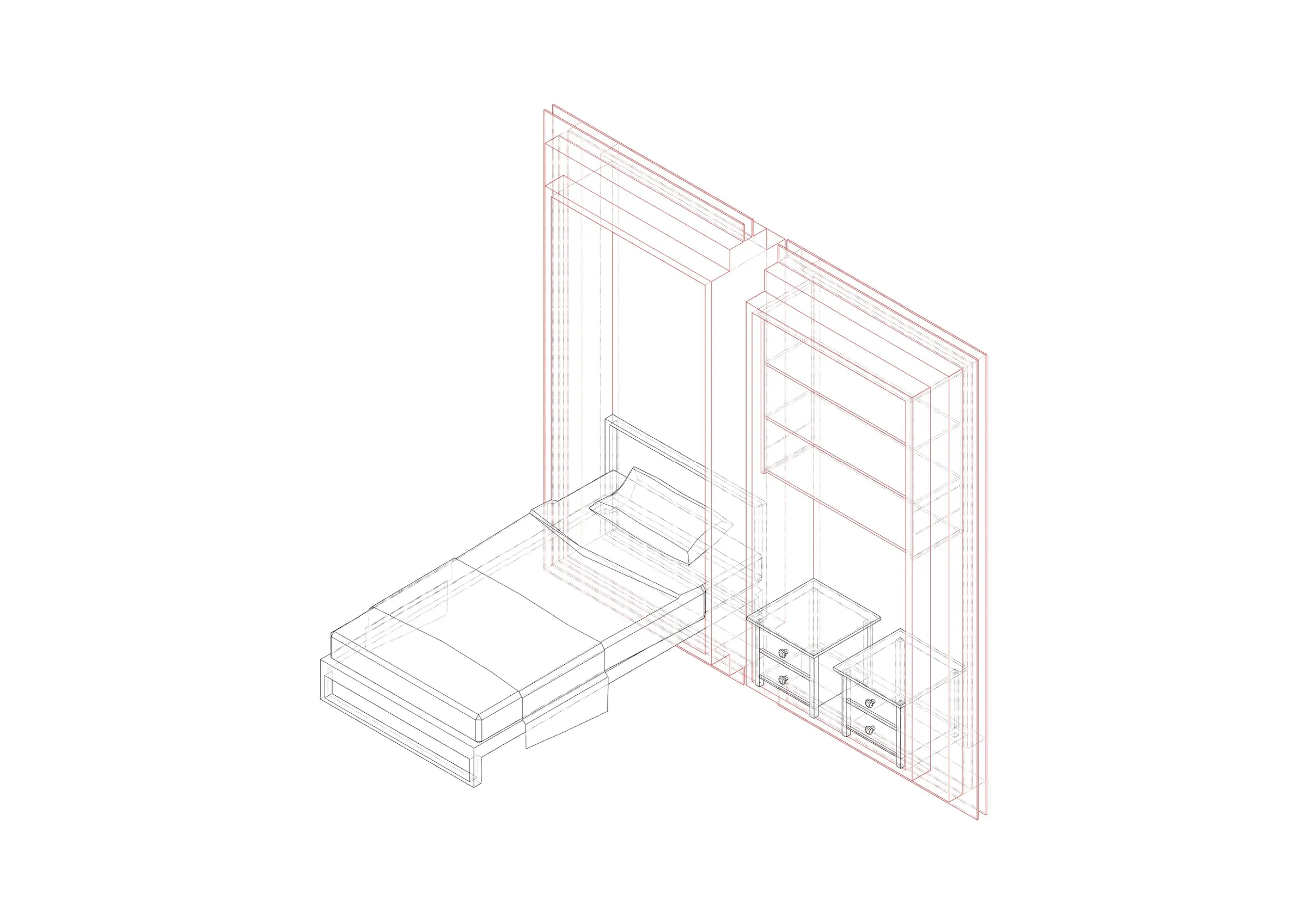
Wall A: openings
Wall A · Openings
Wall B: bed and dressing
Wall B · Bed + dressing
Wall C: toilet
Wall C · Toilet
Wall D: hall
Wall D · Hall
Wall E: master bedroom
Wall E · Master bedroom
Wall F: kitchen
Wall F · Kitchen
Perspective line drawing of the modules
2

Symphony: Football Stadium

B.Arch final-year thesis, NIT TrichyBengaluru, IndiaTimeline: Aug 2023 – May 2024
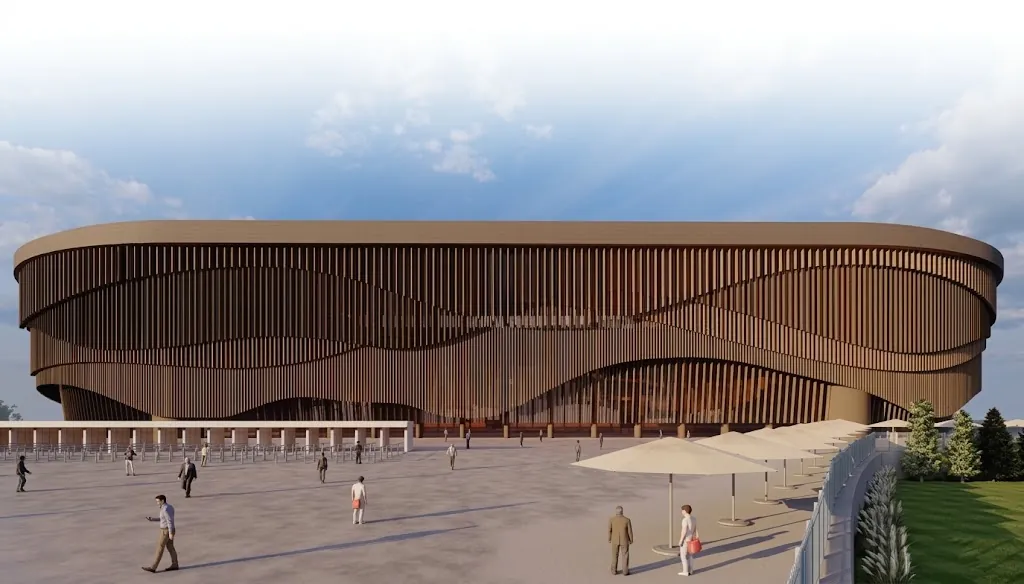
Render of the stadium with a wave-like facade
50,000seat capacity
240,000 m²site area
2023 – 24thesis, Aug to May
Bengaluru FChome club

Macro-level layout

Safe, seamless circulation

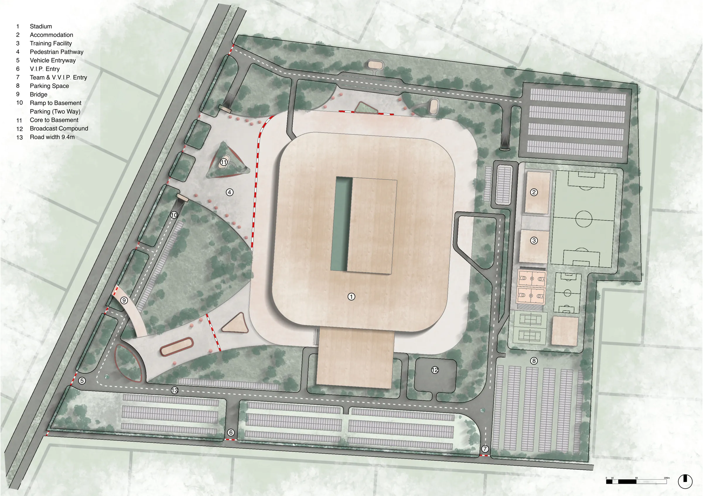
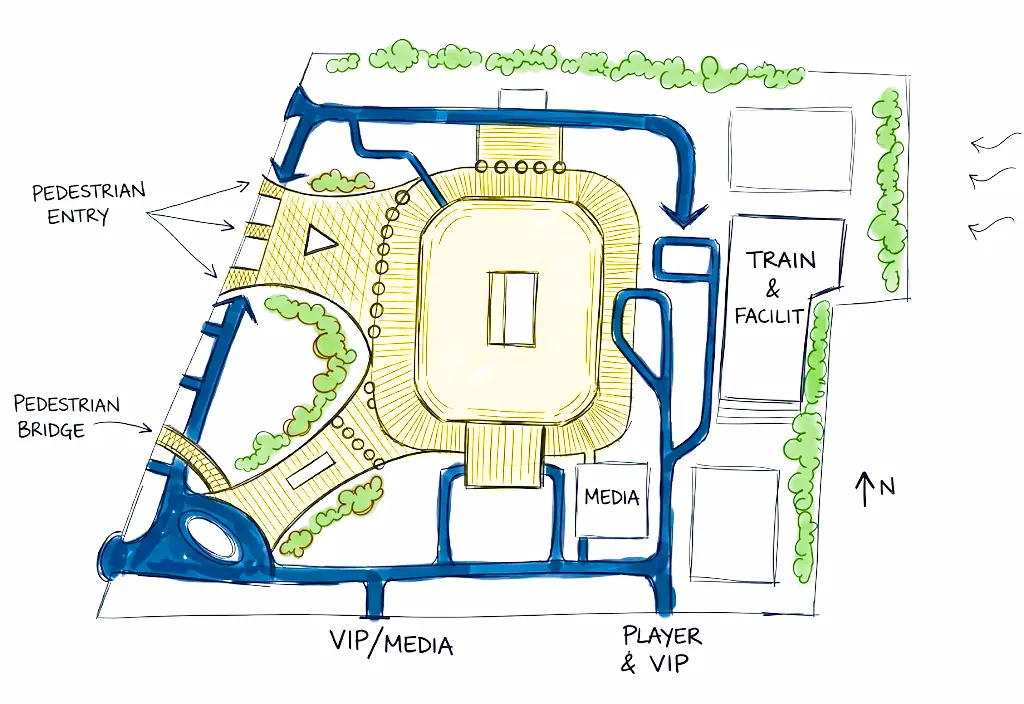
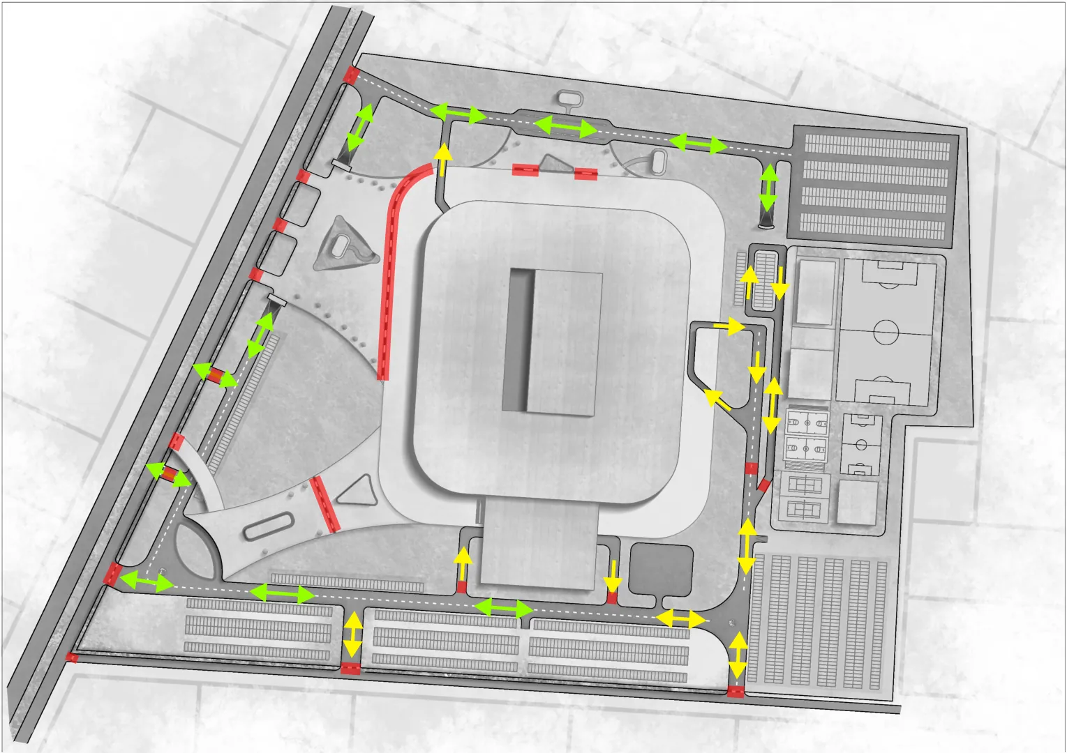
With a capacity of 50,000, the key design factor was safe and seamless circulation of users within and beyond the stadium. Studies of user typology and modes of commuting shaped the layout of the 240,000 m² site.

Pedestrian and vehicular access points are segregated, and for secure movement the pathways are broken down so no one has to circle the whole campus on the same route.

Site plan
Site plan
Pedestrian circulation sketch
Pedestrian circulation
Pedestrian pathwayVehicular pathwayGreen belts
Vehicular segregation diagram
Vehicular segregation
Gates & securityGeneral publicPlayers, media & VIP
Conceptual framework

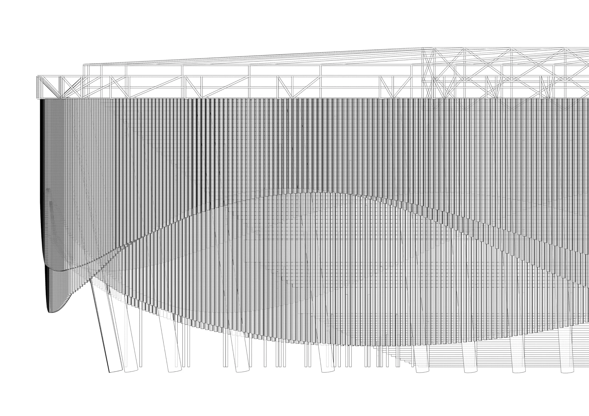
A porous skin of chimes

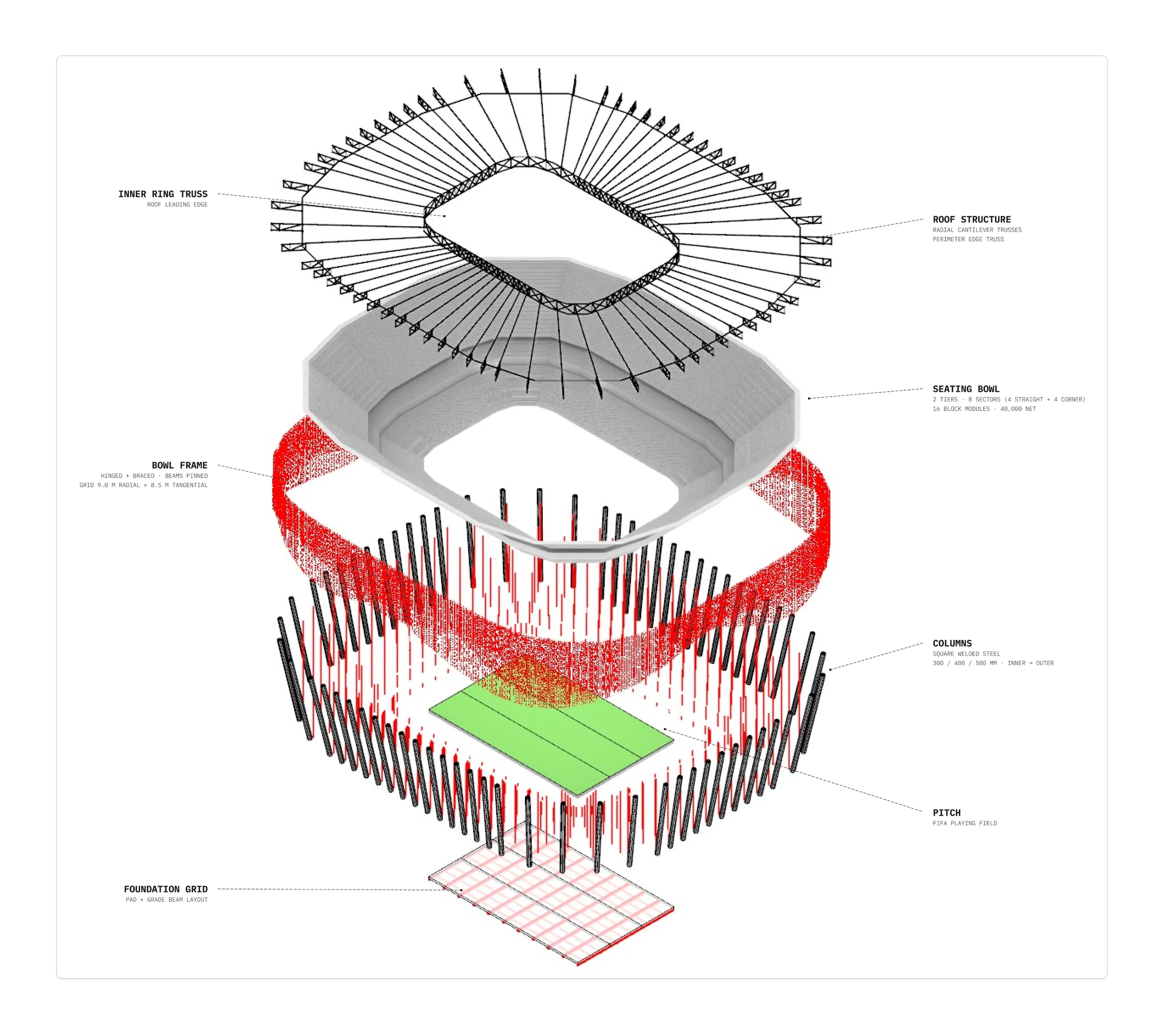
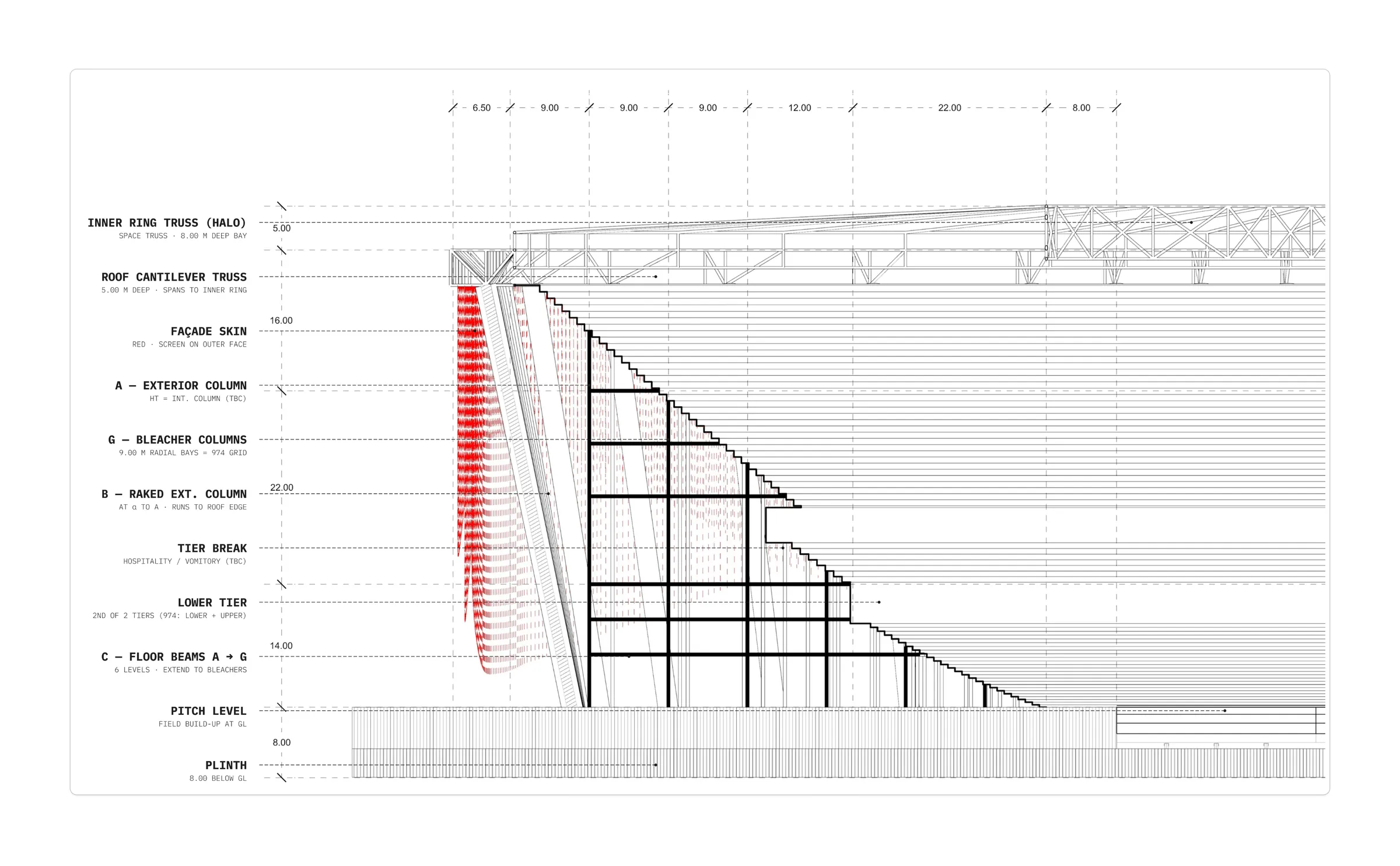
Layered from foundation grid to inner ring truss, the structure builds up from perimeter columns and a raked bowl frame to cantilevered roof trusses around the pitch. The façade wraps it in "chimes": vertical elements hung in overlapping layers, forming a porous skin that filters light and air.

Exploded axonometric of the structure
Axonometric: conceptual framework
Elevation concept
Elevation: concept development
Section of the main stand
Typical section of the main stand

Floor plans

Active on non-match days

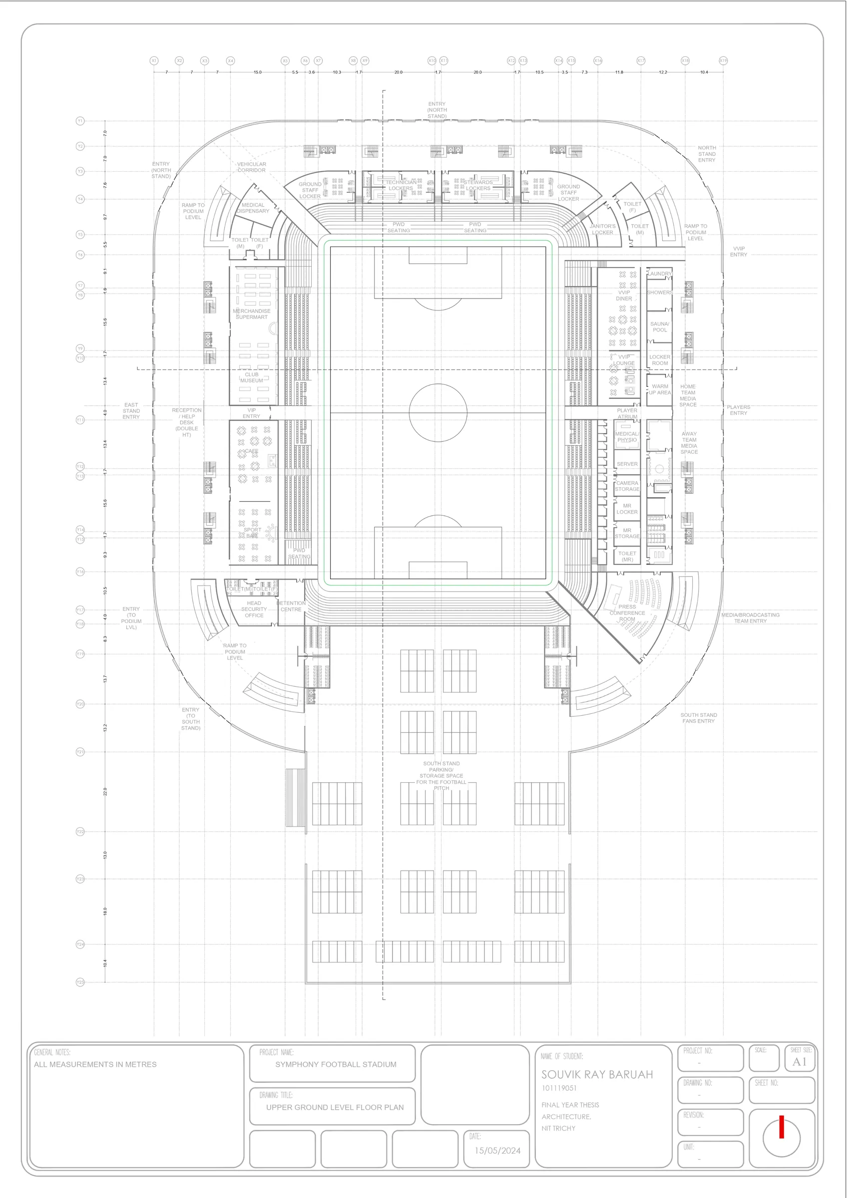
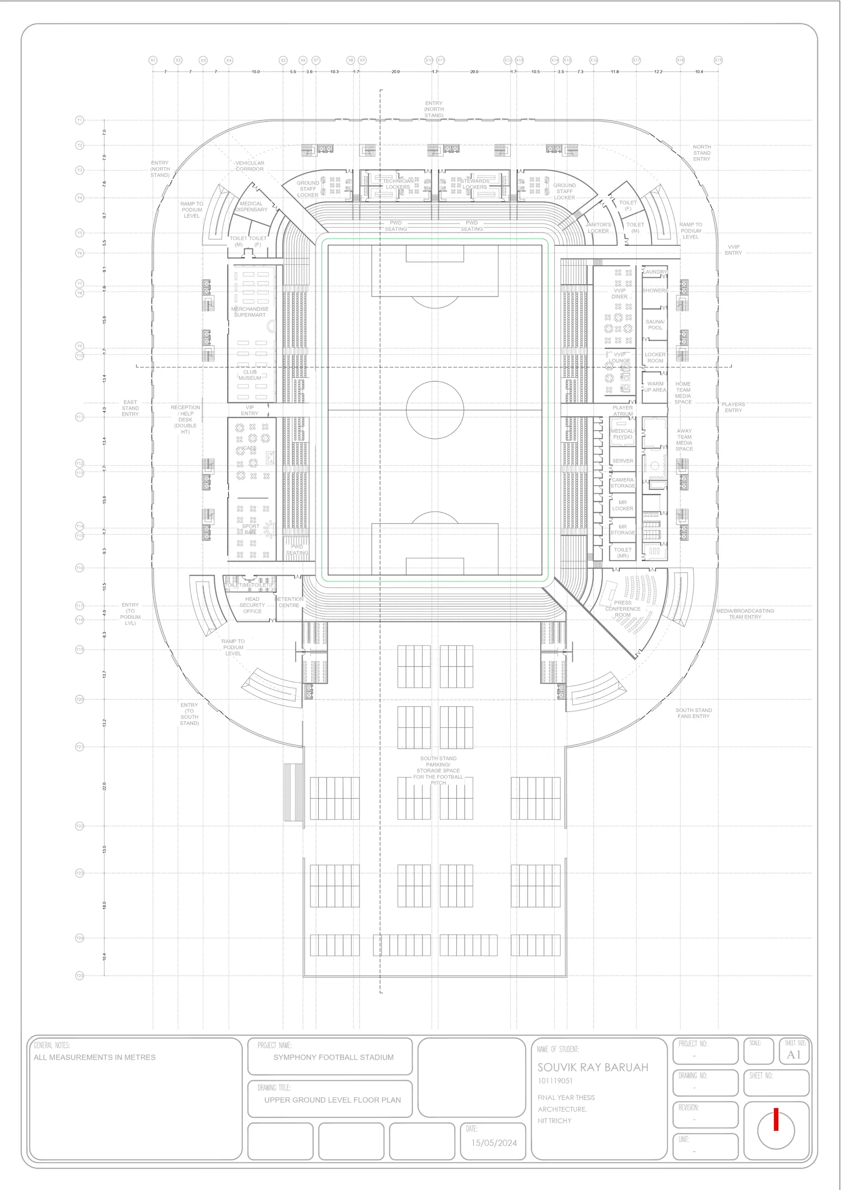
The upper ground level is the operational core, with separate entries for players, media and VVIP guests, alongside fan services such as the club museum, merchandise store, café and sport bar off a double-height reception. Above, the podium level adds stadium-view lounges along both sidelines and a social block with a banquet hall, sport bar and football turf.

Podium-level floor plan
Upper ground-level floor plan
3

Robotics for Ecological Building

Terms 2 & 3 research studio, IAAC (group)Barcelona, SpainResponsibilities: robotic logic drawing, documentation of the robotic process
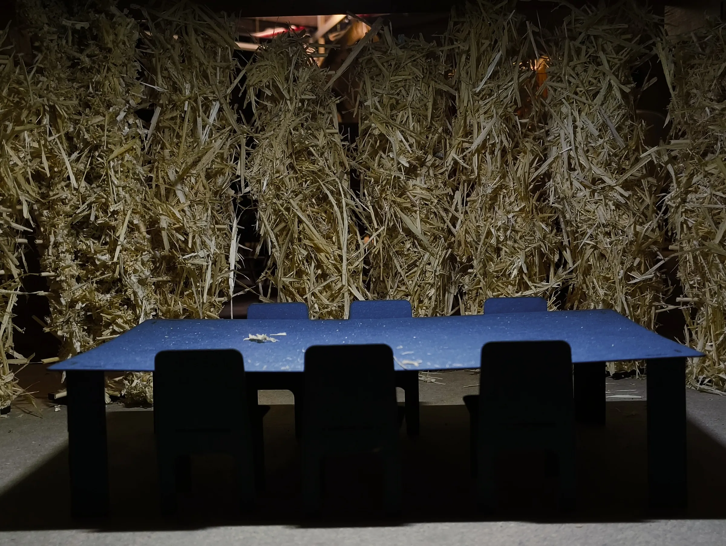
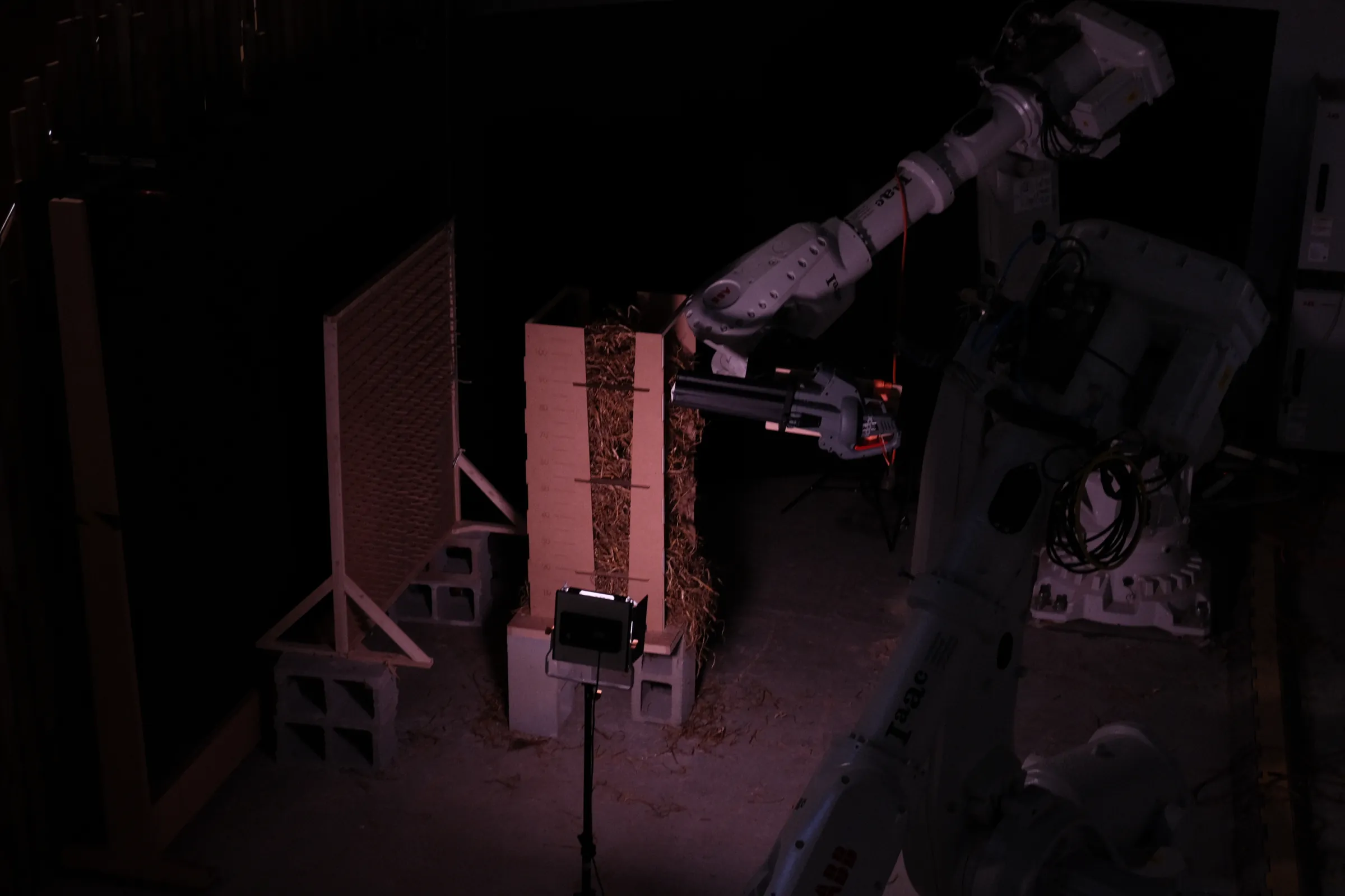
Industrial robot arm with pneumatic end-effector spraying straw

Straw, robotically sprayed

A wall without glue

Straw is one of the most plentiful agricultural by-products, yet it is often burnt or thrown away. This studio asked whether a robot could turn loose straw into a building element without glue or binder.

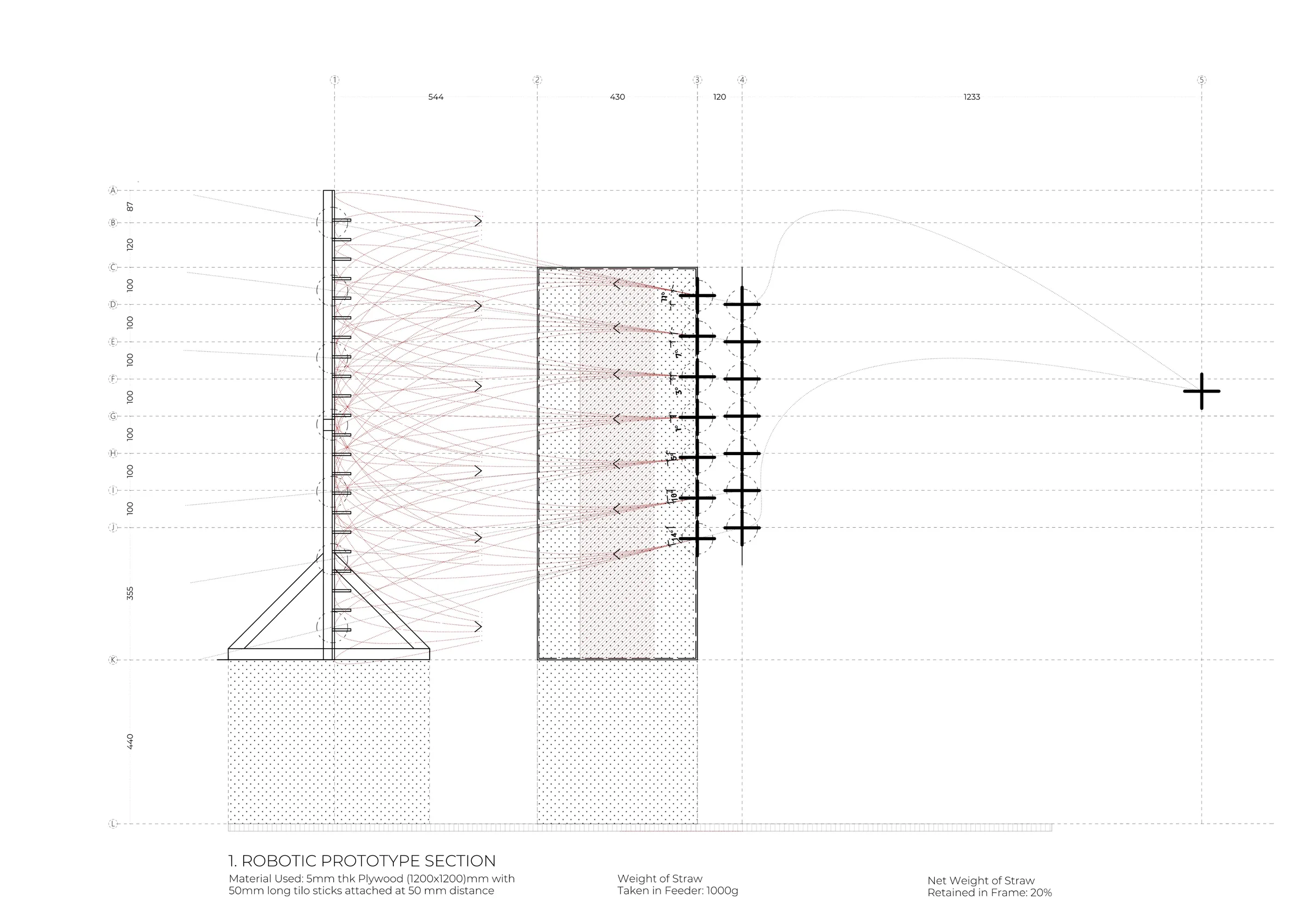
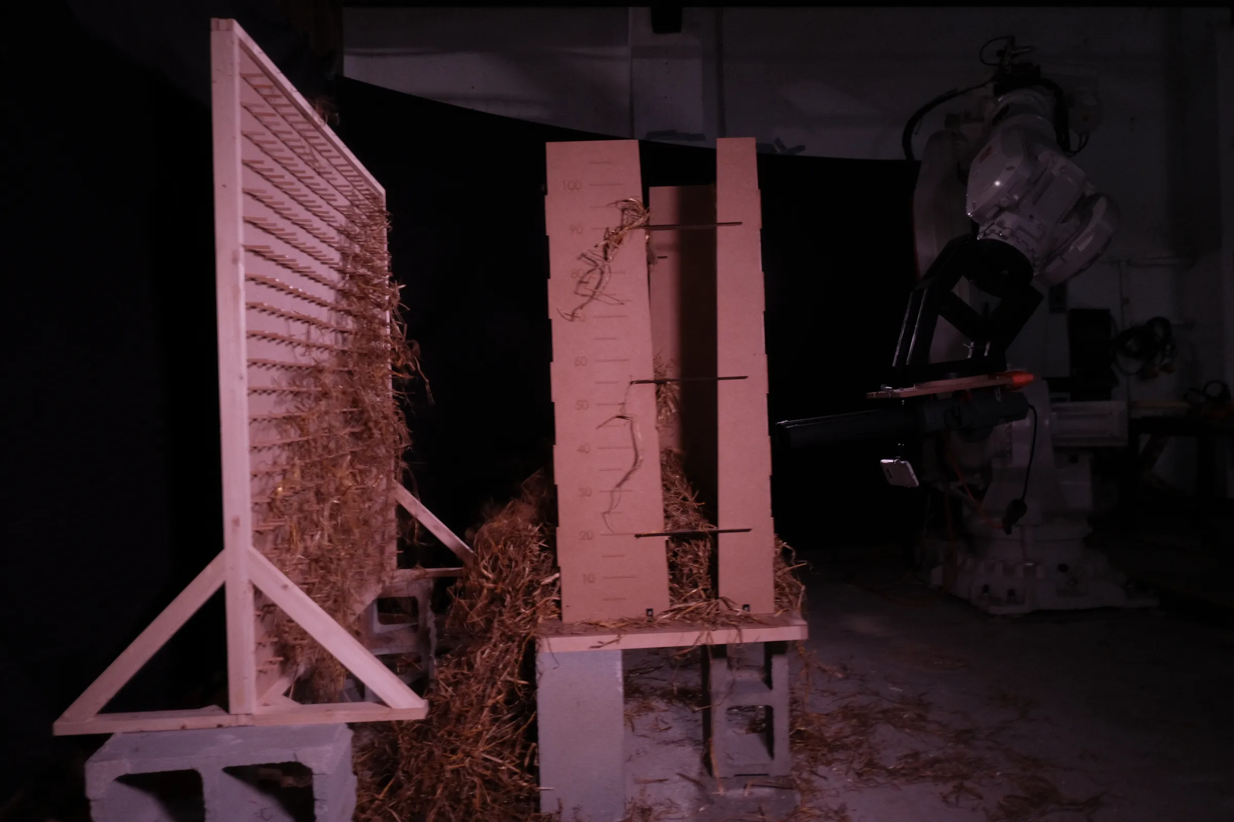
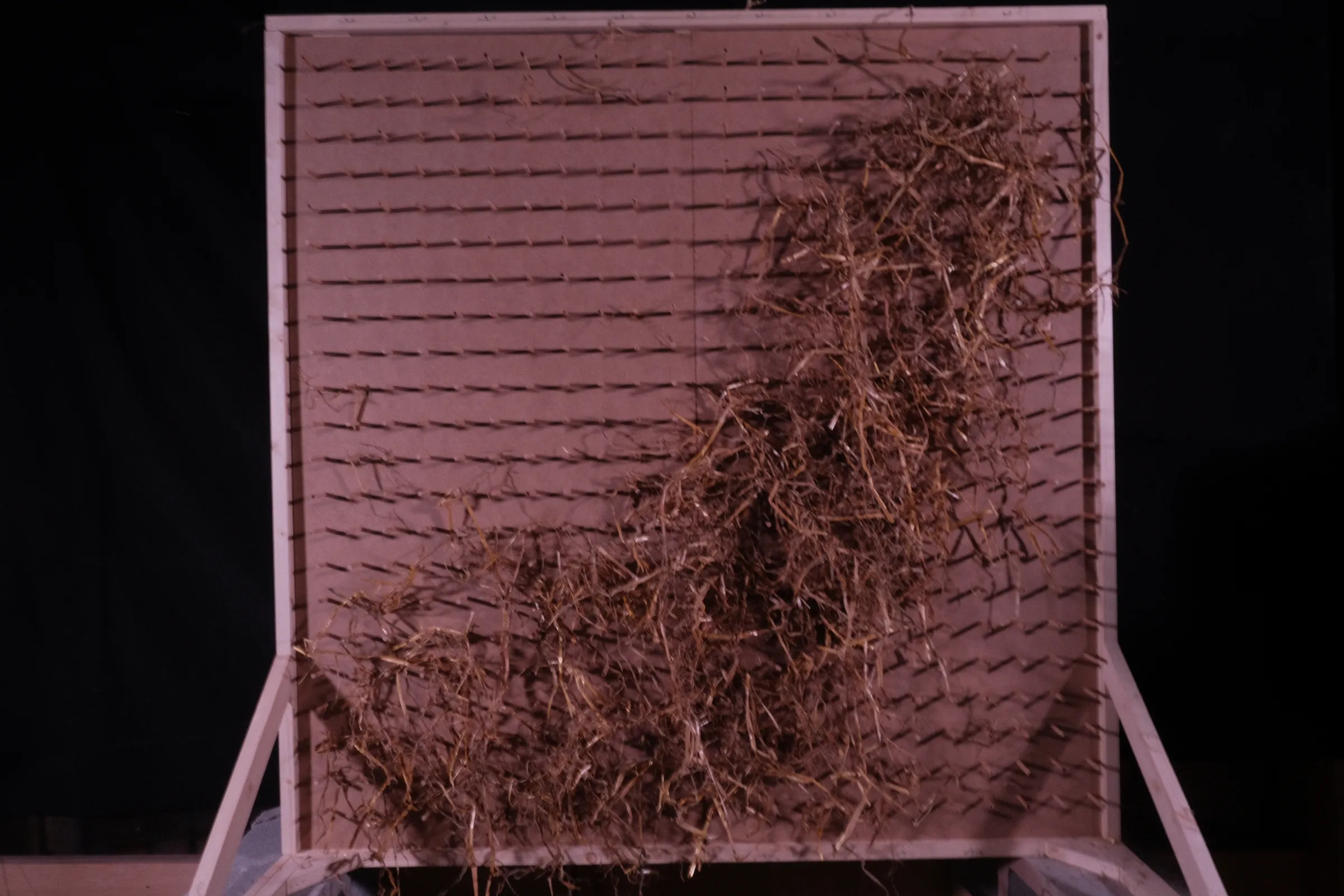
Using an industrial robot arm fitted with a pneumatic end-effector, our team sprayed straw onto a pinned plywood frame, building up a partition wall layer by layer along a digitally planned path.

Straw fed into end-effector→Sprayed by robot arm→Caught on pinned frame→Retention weighed
Prototype section drawing
Prototype 1, section: 50 mm pins at 50 mm spacing
Side view of sprayed frame
Side view after spraying

Logic drawings

Planning every pass

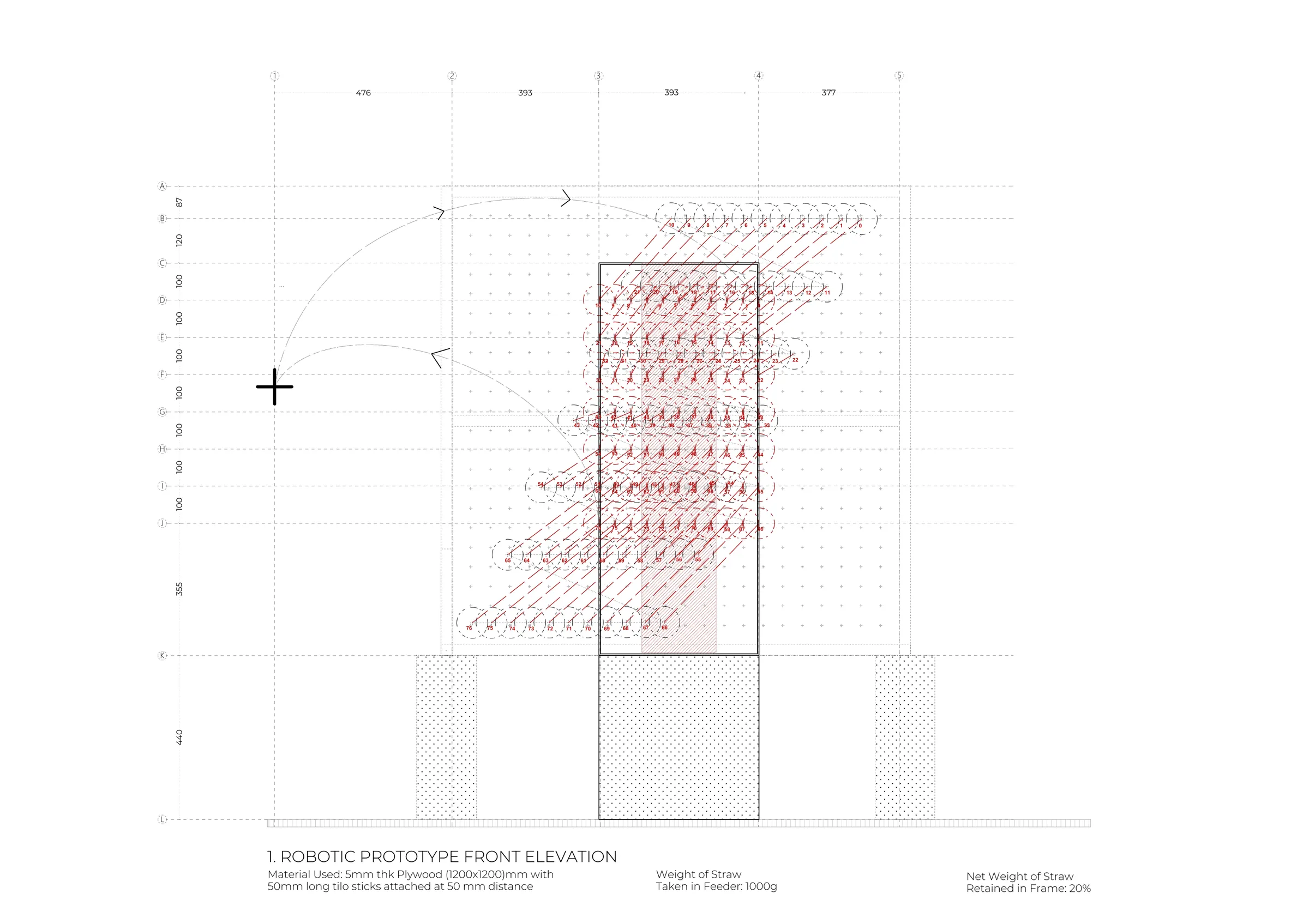
Before any straw was sprayed, the logic drawings set out how the robot would move: its distance from the frame, the spray direction and the order of passes. The toolpath was generated in Grasshopper and converted into robot code. Each run tested how much straw the pins could hold without binder.

Toolpath elevation drawing
Front elevation: Grasshopper toolpath
Front view of sprayed frame
Front view after spraying
1200 × 2200mm frame, 5 mm plywood
50 mmpins at 50 mm centres
1,000 gstraw per run
37%retained on frame

Final prototype

The tree system wall

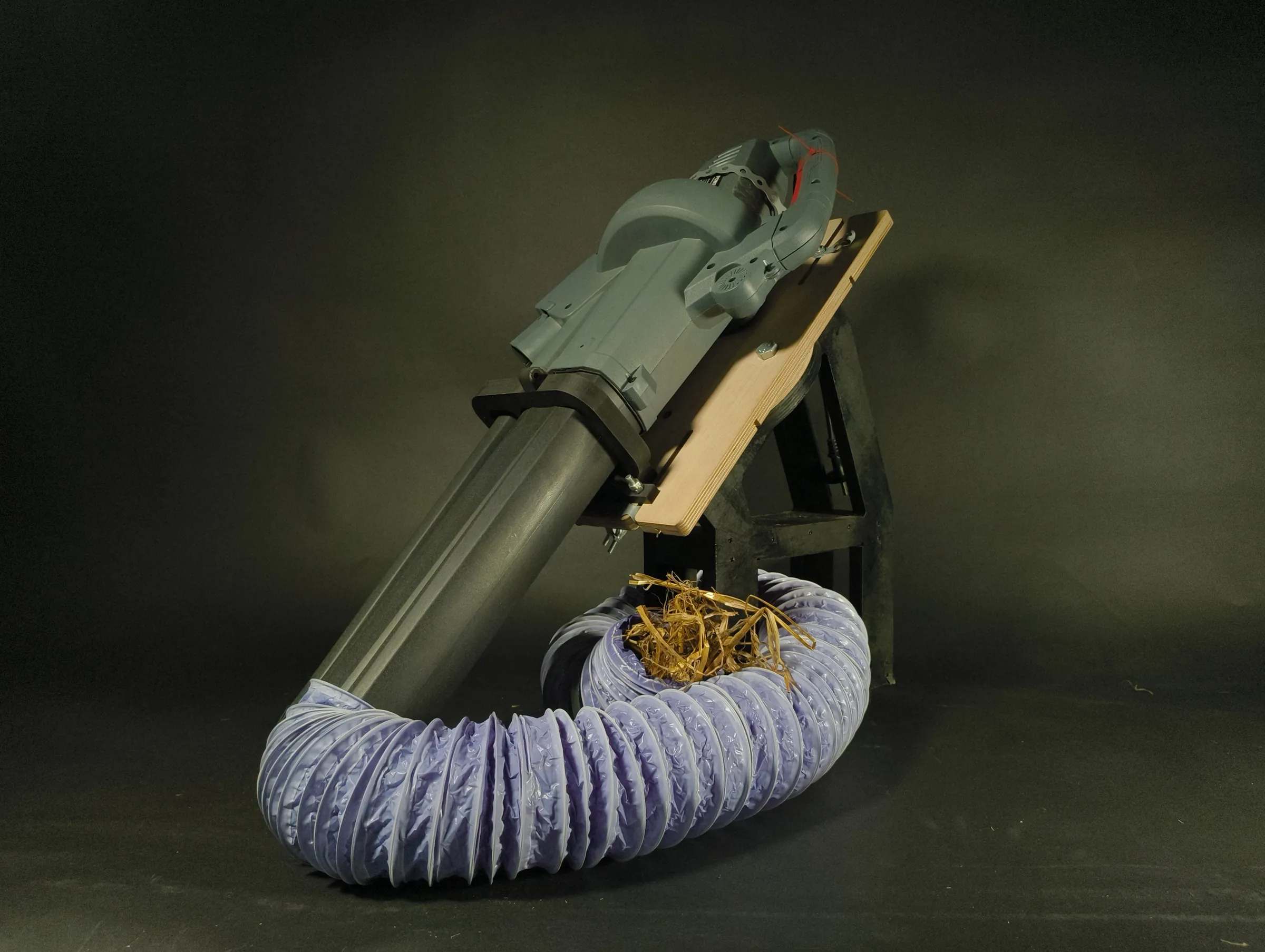
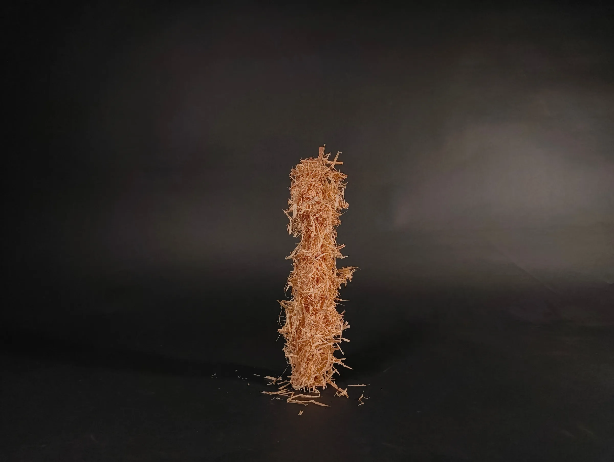
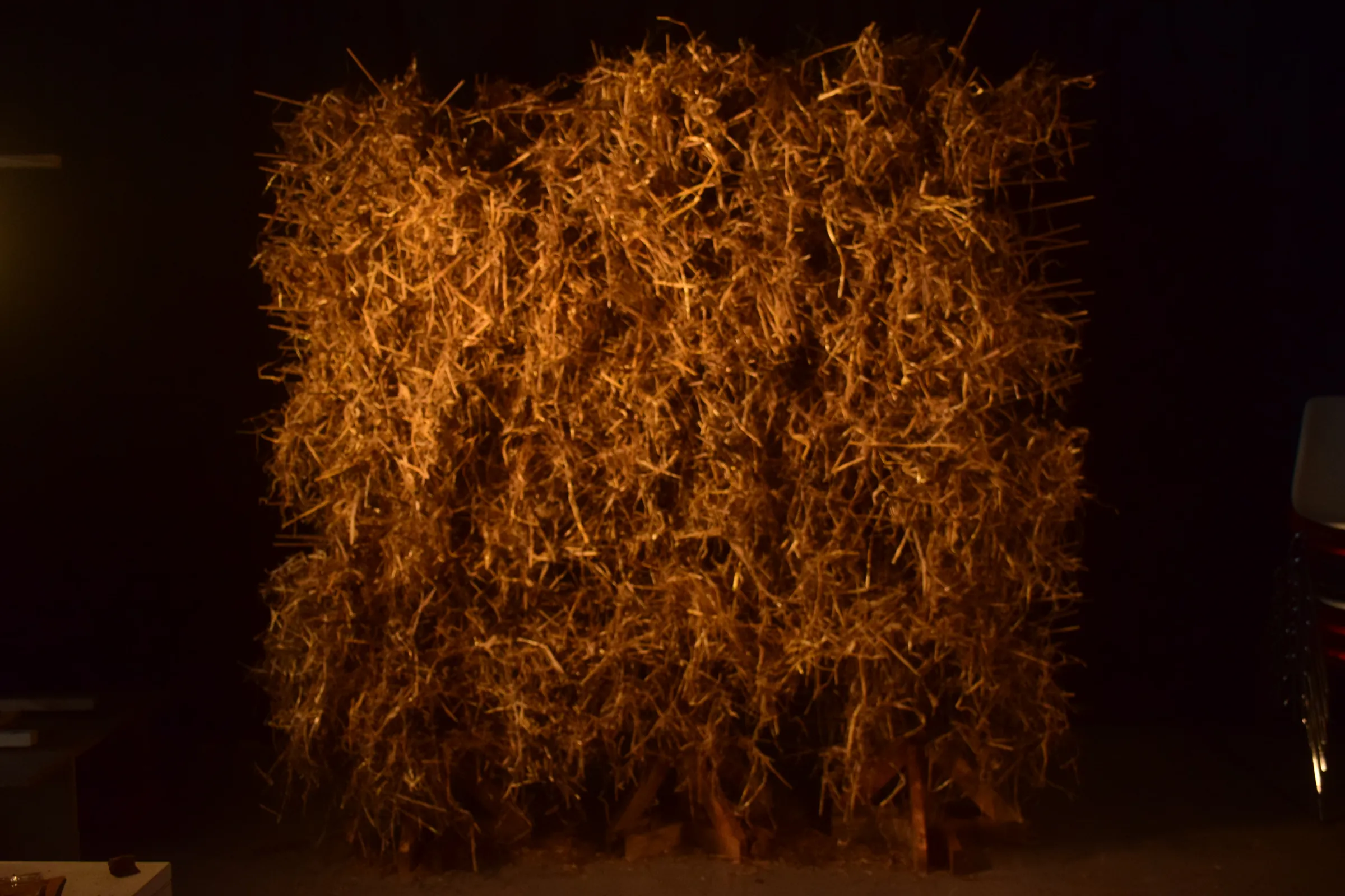
The final prototype replaces fixed panels with a field of branched poles. A modified leaf-blower end-effector shreds loose straw and blows it onto the angled sticks of each pole, where friction alone holds the fibres in place. The poles can be moved and re-sprayed, so IAAC's spaces can be reshaped as needs change: a low-carbon, acoustically absorbent partition made from an abundant by-product.

Modified leaf-blower end effector
End effector · modified leaf blower
Single sprayed pole
Single pole · 1:10 model
Close-up of straw fibres
Fibre interlock
Straw poles around a meeting table
Spatial application
4

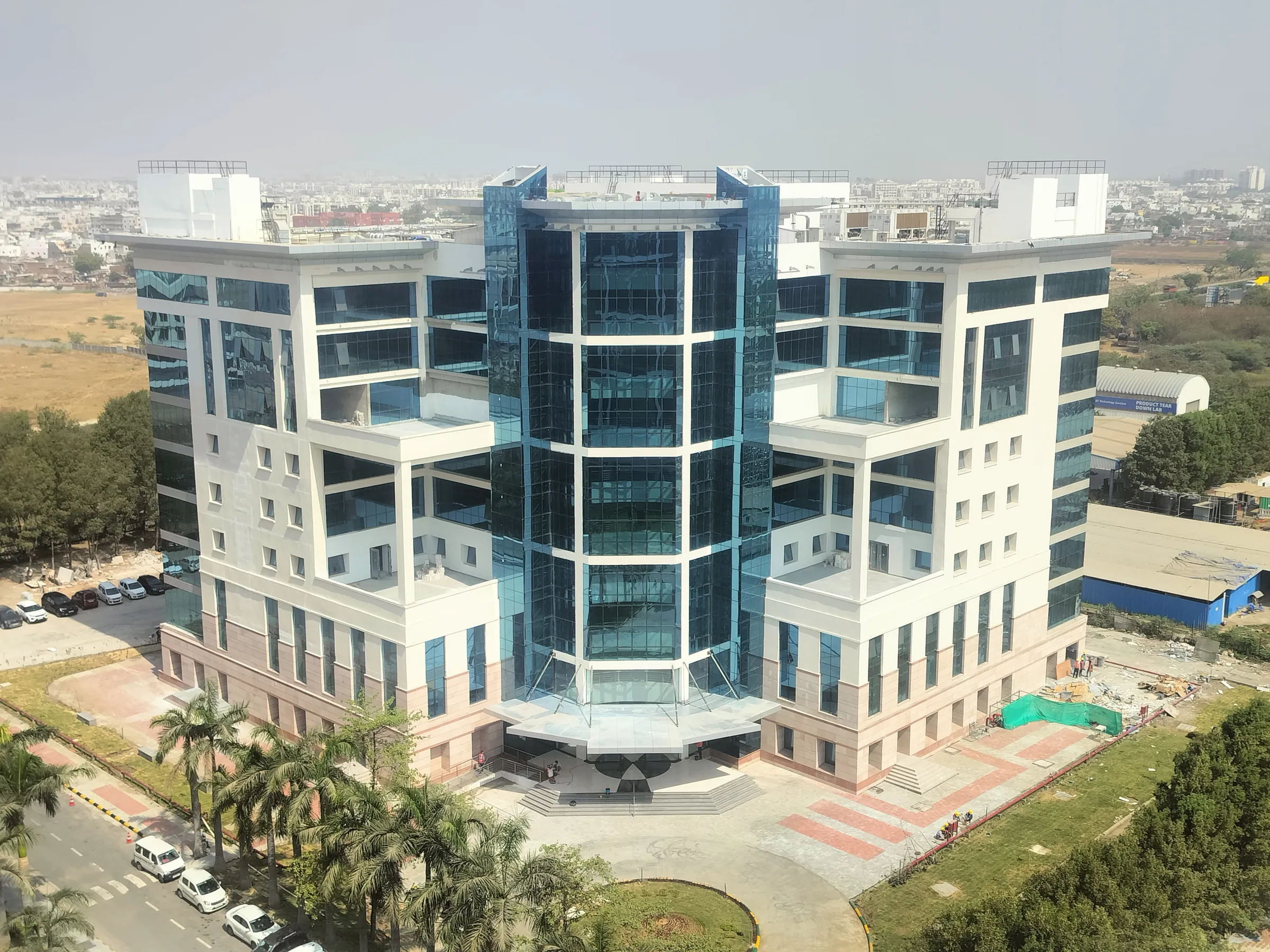
West Block 4, Knowledge City

Professional project, Larsen & Toubro ConstructionVadodara, Gujarat, IndiaRole: graduate architect trainee
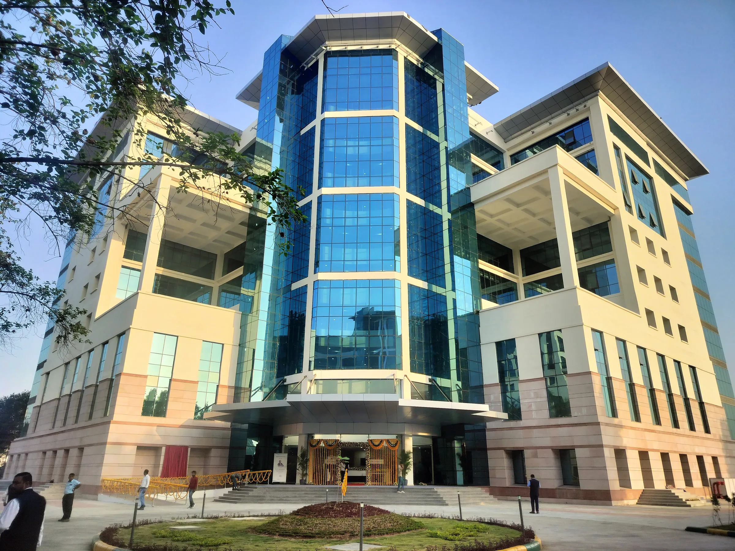
Completed IT campus office building with a glazed central tower
B2+B1+G+8floors
~32,000 m²built-up area
~1,900occupants
Aug 24 – Jun 25IT campus, design-build

Project development

Where drawings meet the building

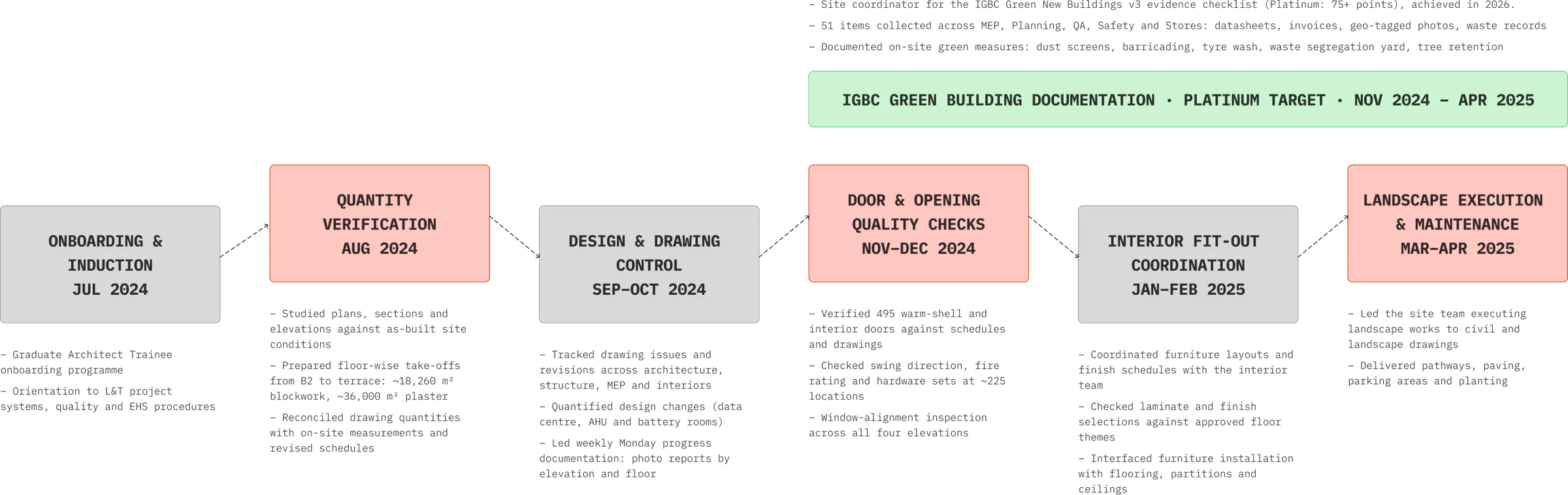
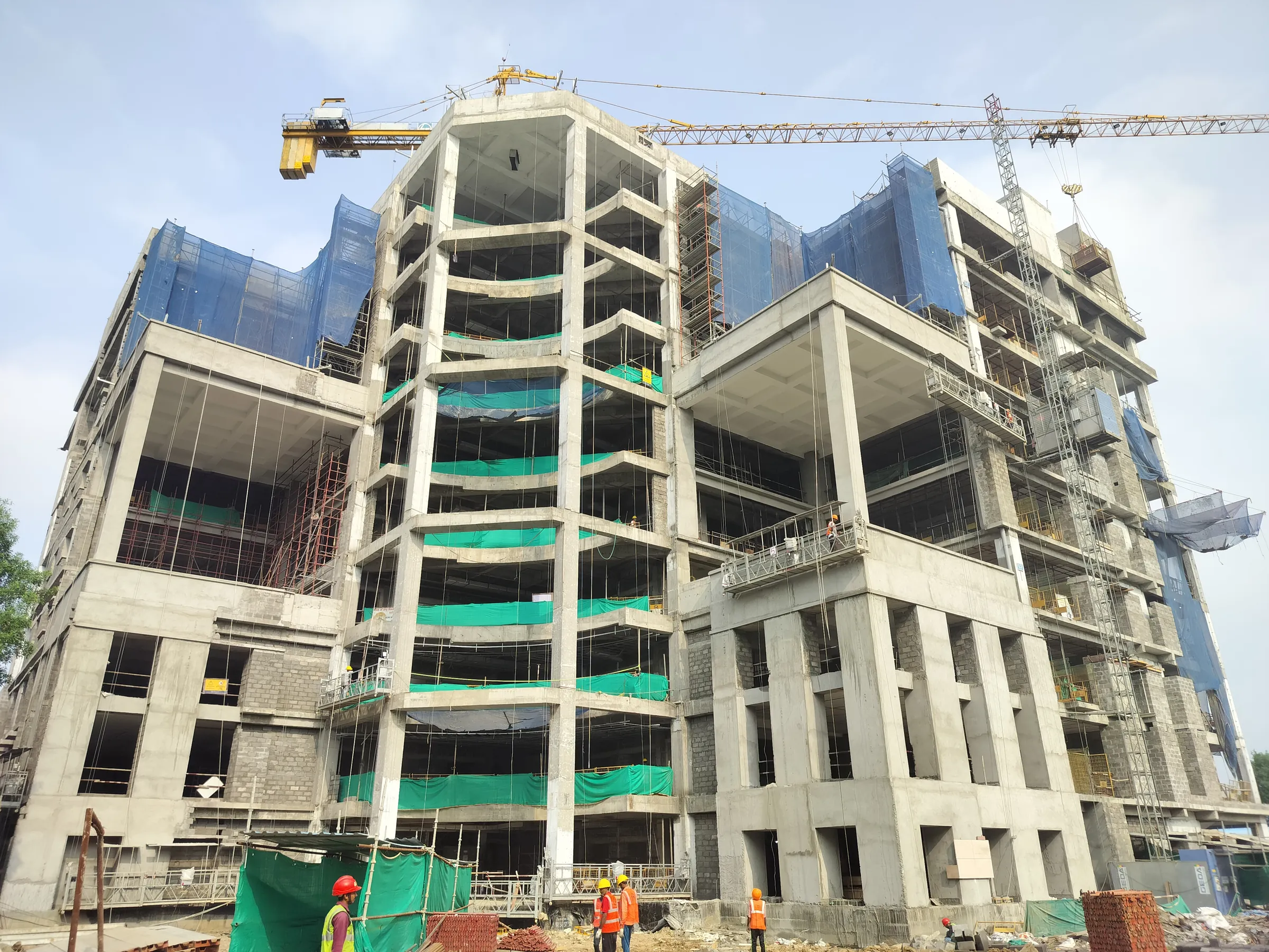
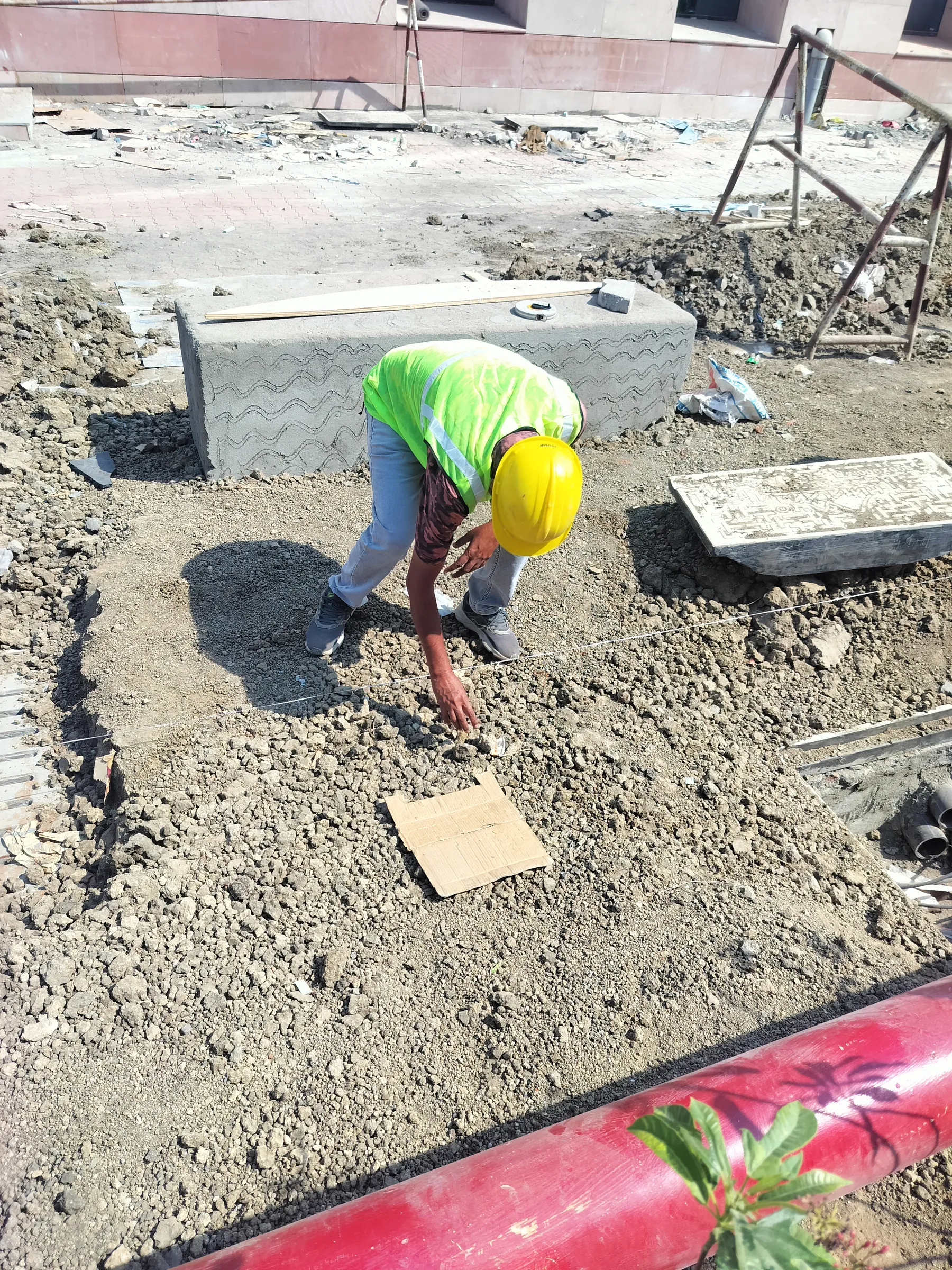
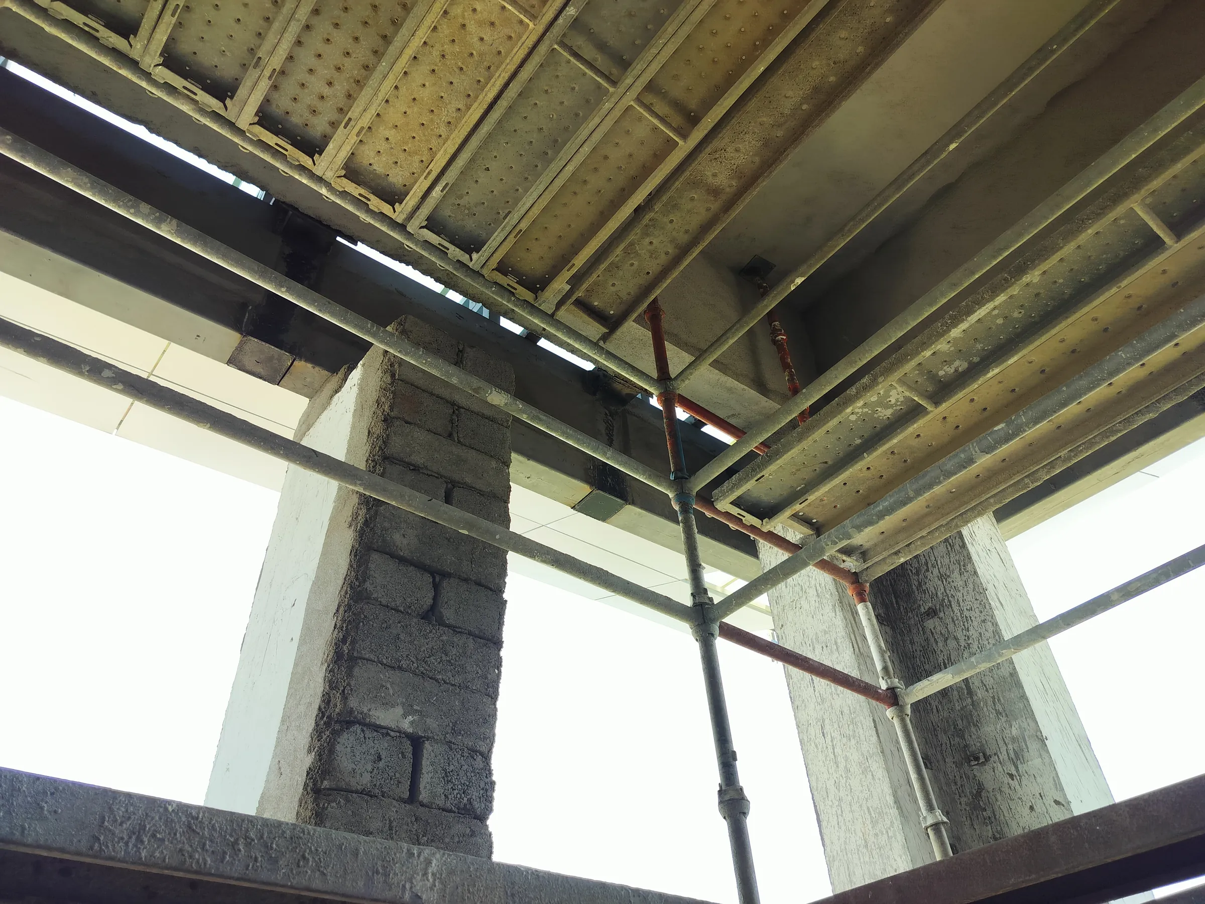
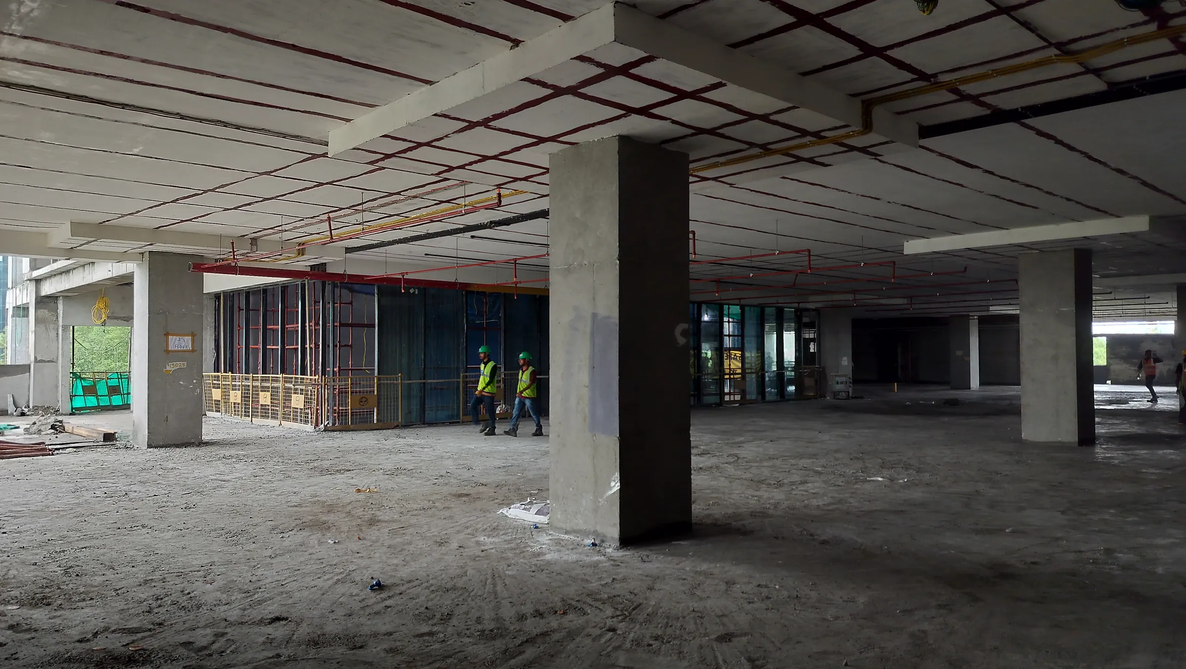
My year with Larsen & Toubro Construction was spent on site, delivering a design-build office building at Knowledge City, Vadodara. I checked quantities against site conditions, carried out quality checks on openings and finishes, and documented the building's progress floor by floor each week.

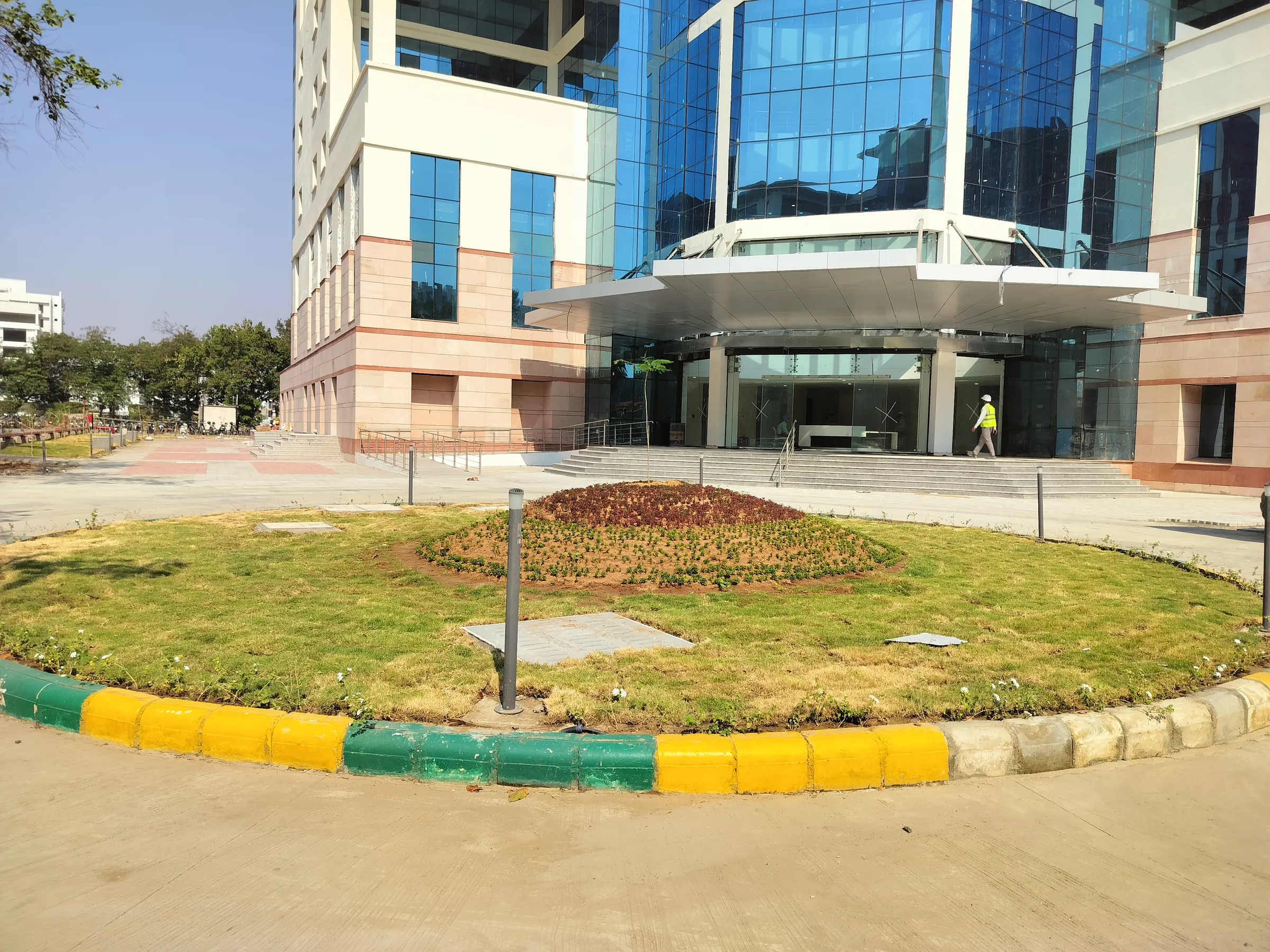
I coordinated green-building documentation for IGBC certification and led a team building and maintaining the site landscape.

Timeline of tasks and roles on site
Site-architect tasks and roles, Jul 2024 – Apr 2025
Building under construction, August 2024 Building nearing completion, April 2025 August 2024
Worker laying landscape on site
Finished landscape at the entrance
Window frame under installation
Openings: window installation checks
Office floor shell
Shell: floor before fit-out
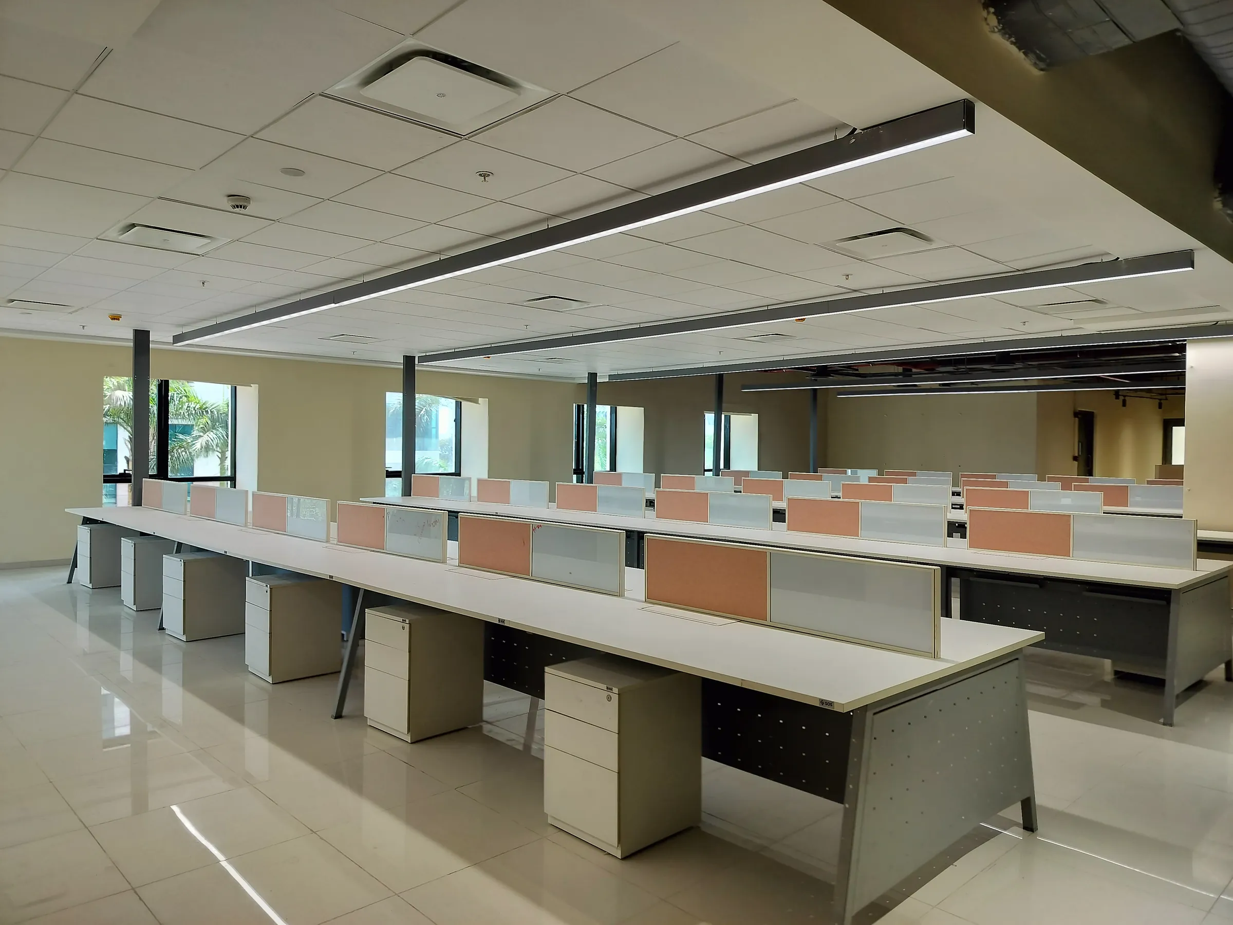
Completed open-plan office
Fit-out: completed workstations
5

Internship

Professional projects, 2+ Design CollaborativeMysuru, Karnataka, IndiaRole: architectural intern, Jan – Jun 2023

First time in practice

Concept to construction

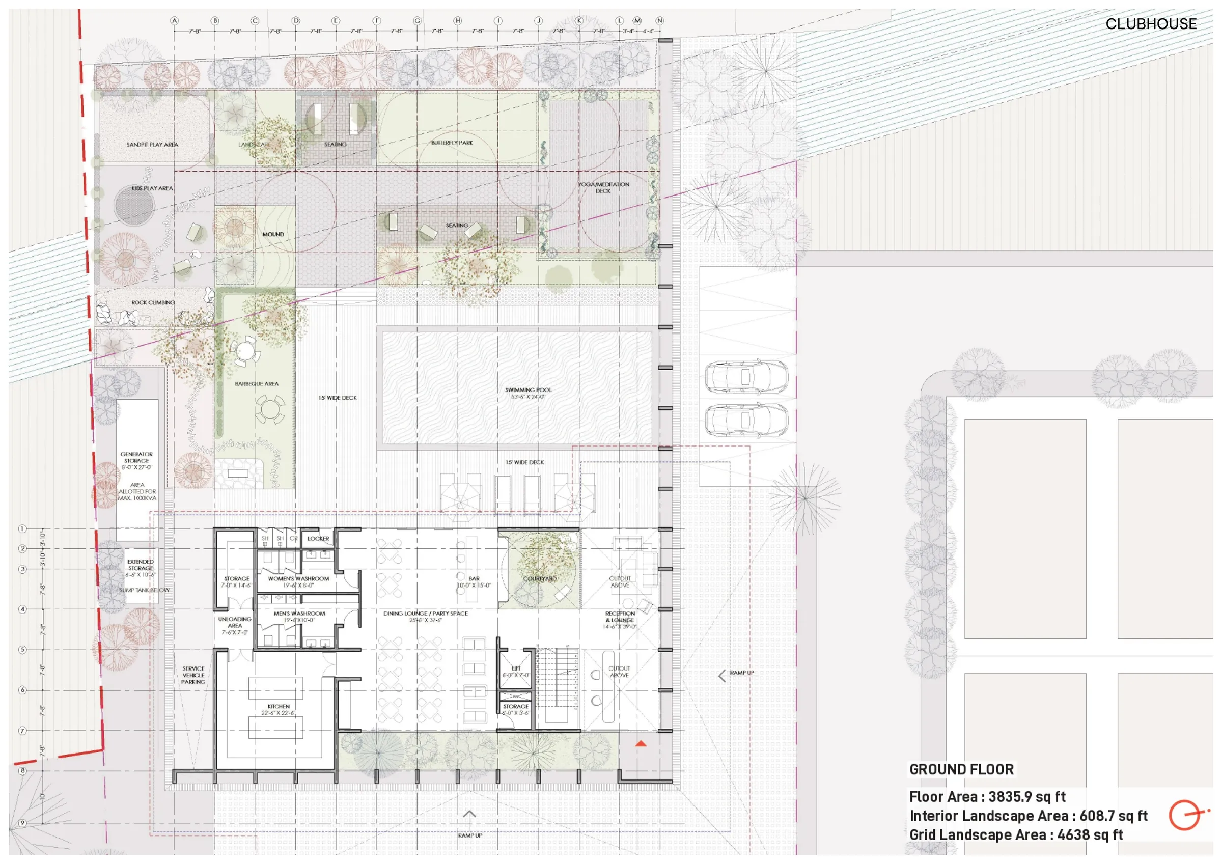
My six months at 2+ Design Collaborative were my first time in practice, working across residential, commercial and masterplan projects. I worked from early concept to construction: drafting conceptual floor plan layouts and preparing good-for-construction (GFC) drawings for interior fit-out details in Rhino and AutoCAD.

Clubhouse ground floor layout
Concept layout, Rhinoceros and AutoCAD
GFC interior fit-out drawing
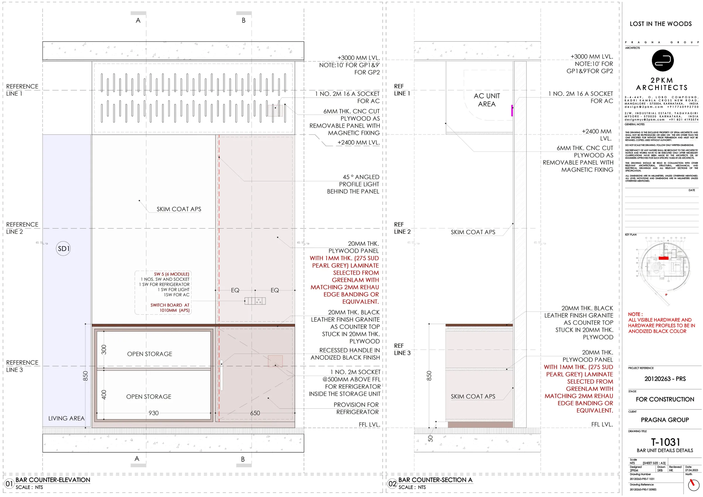
GFC drawing, interior fit-out detail

Let's build something together.

raybaruahsouvik@gmail.com